Flow measurement, Operation, Fig. 5 – Watts TDV User Manual
Page 3: Fig. 6
Valve Size
2
1
⁄
2
3
4
5
6
8
10
12
Number of Rings
5
5
6
9
10
12
18
28
(valve full open)
Flow Measurement
1. Where approximate indication of flow is acceptable the Watts
Series TDV valve can be used.
2. Flow Measurement Valve in Wide Open Position
1. Measure and record the differential pressure across the
valve using a Watts Series PG meter.
CAUTION: Safety glasses should be used.
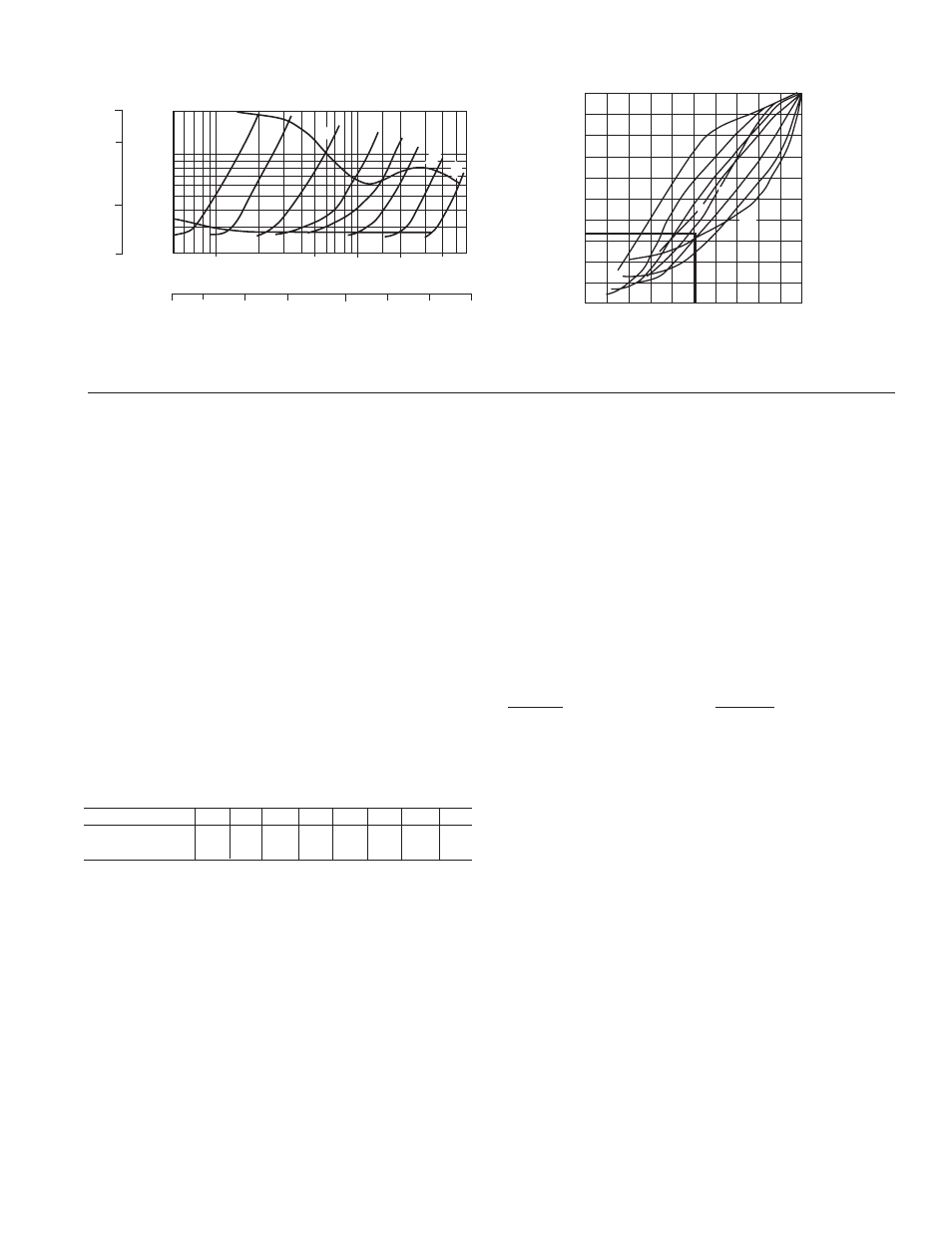
2. Refer to Series TDV Performance Curves with valve in full
open position (Fig. 5).
Locate Pressure Differential on left hand side of chart and
extend line horizontally across to valve size being used.
Drop line vertically down and read flow rate from bottom of
chart.
3. Determining Flow Rate with Valve in Throttled Position
1. Record the size of valve and stem position using the Flow
Indicator Scale (on page 3) Calculate percentage of valve
opening referring to table below:
2. Measure and record the differential pressure across the
valve in the throttled position.
3. Locate percentage of valve opening on the bottom scale of
Flow Characteristic Curve (Fig. 6). Project line vertically up
to intersect with the Valve Characteristic Curve and from
this point project line horizontally across to the left of the
chart and record the percentage of maximum flow rate.
4. On the Series TDV Performance Curve (Fig. 5) locate the
differential pressure obtained in Step 6.3.2 and project line
horizontally across to intercept with Valve Performance
Curve. Drop a line vertically down to read the flow rate at
the bottom of the chart.
5. To calculate flow rate of valve in the throttled position, mul-
tiply the flow rate from Step 6.3.4 by the percentage flow
rate from Step 6.3.2 divided by 100.
Example: Valve size 4 in.
Differential Pressure in 5.4 ft. (1.65m)
Number of rings open = 3, 3 rings ÷ 6 rings x 100 =
50% throttled
• From the Performance Curve (Fig. 5), a 4 in. valve
with 5.4 ft. pressure drop (1.65m) represents a flow of
400 USgpm (25.2 l/s).
• From Flow Characteristic Curve (Fig. 6), a 4 in. valve,
50% open, represents 34% of maximum flow.
• Approximate flow of a 4 in. valve, with a 5.4 ft. (1.65m)
pressure drop when 50% throttled is:
400 x 34 = 136 USgpm
(25.2 x 34
= 8.57 l/s)
100
100
NOTE: To prevent premature valve failure it is not recommended
that the valve operate in the throttled position with more than
25 ft. pressure differential. Instead the pump impeller should be
trimmed or valves located else where in the system to partially
throttle the flow.
Operation
1. To assure tight shut off the valve must be closed using a
wrench with 25 to 30 ft./lbs. of torque.
2. To assure trouble-free check valve operation and shut off
operation, the valve should be periodically opened and
closed to keep valve seat and valve disc guide stem free of
build up of system contaminants.
3
Fig. 5
Pressure Drop (MH
2
O)
20
10
5.0
2.0
50
100
500
1000
2000 4000 6000
3.0
5.0
10
20
50
100 200
400
20
10
5.0
2.0
Flowrate (USGPM)
Pressure Drop (Ft.
WG)
Fig. 6
100
80
60
40
20
0
0
20
40
60
80
100
12”
8”
10”
6”
5”
4” 3”
2
1
⁄
2
”
Percent of Max Flow
Inherent Flow Characteristic Curve with Valve in Throttled Position
Series TDV Performance Curve with Valve in Full Open Position
Percent of Full Open
5
3
1
.5
Flowrate (L/Sec)
2
1
⁄
2
”
3”
4”
5”
6”
8”
10”
12”