Watts flange adapter installation, Pressure - temperature limits, Field conversion – Watts TDV User Manual
Page 2: Flow indicator scale
B
A
2
Watts
Flange Adapter Details
125 psi/150 psi
Ductile Iron
Valve
Bolt
Size
No.
Size
2
1
⁄
2
4
5
⁄
8
3
4
5
⁄
8
4
8
5
⁄
8
5
8
3
⁄
4
6
8
3
⁄
4
8
8
3
⁄
4
10
12
7
⁄
8
12
12
7
⁄
8
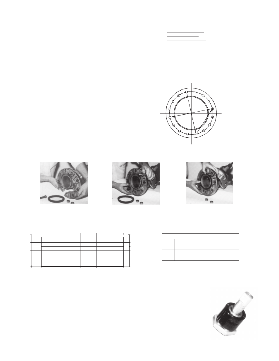
Watts Flange Adapter Installation
1. Position the two halves of Watts Flange Adapter on the valve
body (Fig. 1) ensuring that the lugs on each half of the flange
adapters are located between the anti-rotation lugs on the
valve body. Insert two bolts of specified size (Table 1) to
secure the halves of the flange adapter to the valve body (Fig.
2). The gasket cavity should face out to the adjoining flange.
2. Lubricate the inner and outer diameter of the gasket with the
lubricant provided or a similar
non-petroleum base water
soluble grease.
3. Press the gasket firmly into the flange cavity ensuring that
the sealing lip is pointed outward. When in place, the gasket
should not extend beyond the end of the pipe (Fig. 3).
4. Position the adjoining flange or the pipe to the Watts Flange
Adapter and install the remaining bolts. The two locking bolts
should be tightened first in order to position the flanges cor-
rectly as shown in Fig. 1.
NOTE: Care should be taken to ensure that the gasket is not
pinched or bent between flanges.
5. Tighten remaining nuts evenly, following bolting instructions
(Fig. 4), so that the flange faces remain parallel. Flange bolts
should be tightened to 70 ft./lbs. torque minimum to assure
firm metal-to-metal contact. When raised face flanges are
used, there will be a gap between the faces of the outer
diameter.
6. Flange gaskets are not interchangeable with other mechanical
pipe couplings or flange gaskets.
Start
1
2
3
4
5
10
11
12
13
6
7
14
15
16
8
9
Table 1
Fig. 4
Pressure - Temperature Limits
-46° -29° -18°
10°
38°
66°
93°
110°
-50° -20° 0°
50°
100°
150°
200° 230°
400
375
300
250
200
100
0
2760
2585
2070
1724
1380
690
250
Temperature °C
Temperature °F
Pressure psi
Pressure kP
a
A
B
Fig. 2
Fig. 3
Fig. 1
Field Conversion
(Straight to Angle pattern valve)
1. Open valve at least one complete turn.
2. Remove the body bolts from valve body using Allen Key
3. Rotate one half of the valve body 180° making sure the lower
valve seat and O-ring stay in position. Inspect the O-ring for
any cuts or nicks and replace if necessary.
4. Replace body bolts and torque evenly to 70 ft./lbs.
Flow Indicator Scale
The valve stem with its grooved rings
and positioning sleeve indicates the
throttled position of the valve. The quar-
ter turn graduations on the sleeve, with
the scribed line on the stem, provide for
approximate flow measurement.
NOTE: The valve is shipped in the
closed position. The indicator on
the plastic sleeve is aligned with the
vertical scribed line on the stem.
Recommended Bolt Tightening Procedure
Legend
Watts Ductile iron flange
adapters for ANSI 150# flanges
Grooved end with 375 psi rated
pipe coupling