Watts CSM-91-INS User Manual
Insulation systems, For balancing and flow measurement applications, Sizes: 2
For Balancing and Flow Measurement Applications
ES-CSM-91-INS
Job Name –––––––––––––––––––––––––––––––––––––––––––
Contractor ––––––––––––––––––––––––––––––––––––––––––––
Job Location –––––––––––––––––––––––––––––––––––––––––
Approval –––––––––––––––––––––––––––––––––––––––––––––
Engineer –––––––––––––––––––––––––––––––––––––––––––––
Contractor’s P.O. No. –––––––––––––––––––––––––––––––––––
Approval –––––––––––––––––––––––––––––––––––––––––––––
Representative ––––––––––––––––––––––––––––––––––––––––
Insulation Systems
Sizes: 2
1
⁄
2
" – 6" (65 – 150mm)
Watts Insulation Systems are available in sizes 2
1
/
2
" – 6"
(65 – 150mm) to suit series CSM-91 circuit balancing valves
and series TDV Triple Duty Combination Valves.
The outside shell is a preformed, removable PVC jacket to meet
ASTM D 1784/class 14253-C, MEA #7-87, ASTM-E-84 and
ASTM-136 with a flame spread rating of 50 or less. There is pro-
vided sufficient mineral fiberglass insulation to meet ASHRAE
90.1-1989 specifications in operating conditions with Maximum
Fluid Design Operating Temperature Range of 141˚F – 200˚F
(61˚C – 93˚C) and Mean Rating Temperature of 125˚F (52˚C).
Materials
Outside Shell (2): Zeston 2000 PVC
Insulation Batten: Mineral Fiberglass
Fastener (4): Stainless steel
Dimensions
CSM-91-INS
Fig. 1
Fig. 2
Fig. 3
Fig. 4
ES-CSM-91-INS 0317
© Watts Regulator Company, 1996
Printed in U.S.A.
Watts product specifications in U.S. customary units and metric are approximate and are provided for reference only. For precise measurements,
please contact Watts Technical Service. Watts reserves the right to change or modify product design, construction, specifications, or materials with-
out prior notice and without incurring any obligation to make such changes and modifications on Watts products previously or subsequently sold.
USA: 815 Chestnut St., No. Andover, MA 01845-6098; www.wattsreg.com
Canada: 5435 North Service Rd., Burlington, ONT. L7L 5H7; www.wattscda.com
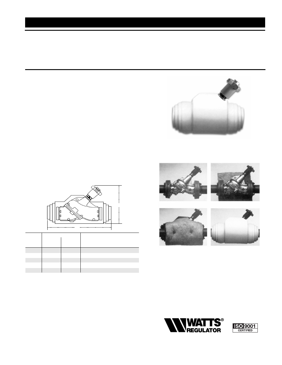
1. Wrap fiberglass insulation around valve keeping insulation
tight around valve neck and body as shown in figs. 2 & 3.
2. Cut out insulation around pressure taps so that when diag-
nostic checks are required, plugs are visible when outside
shell is removed as shown in fig. 3.
3. Slide 2-Piece outer shell over insulation snugly and then use
fastening tacks on top and bottom to secure shell as shown
in fig. 4.
Size (DN)
Dimensions
L x W x T
A
B
Insulation Batten Size
in.
mm
in.
mm
in.
mm
in.
mm
2
1
/
2
65 20
1
/
2
521
10
254
32 x 15 x 1
1
/
2
813 x 381 x 38
3
80
20
508
11
279
37 x 15 x 1
1
/
2
940 x 381 x 38
4
100 22
1
/
2
572 12
1
/
2
318
40 x 17 x 1
1
/
2
1016 x 432 x 38
5
125
26
660
14
356
48
1
/
2
x 21 x 1
1
/
2
1232 x 533 x 38
6
150 30
1
/
2
775
16
406 51
1
/
2
x 22
1
/
2
x 1
1
/
2
1308 x 572 x 38
A
B
Installation Instructions