Installation fig. 2, Fig. 1 fig. 4, Fig. 3 – Watts FV-4 User Manual
Page 2: Maintenance, Operation: important, Dimensions – weights
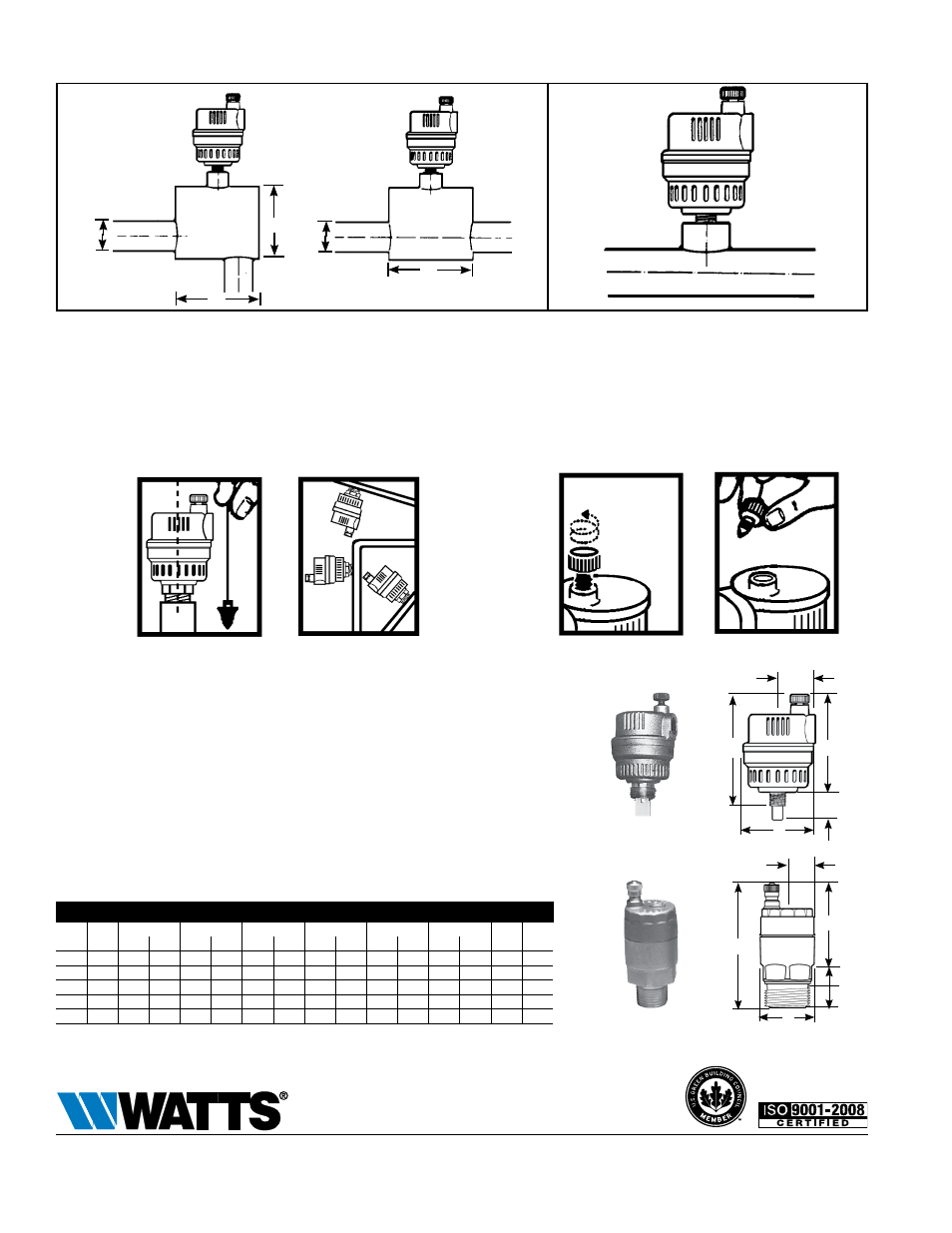
Installation
Fig. 2
*2.5 times pipe ID
ID = Inside Dimensions
*
*
Pipe
ID
Pipe
ID
Figure 1 shows the installation of the FV-4M1 for the venting of
air while the fluid is circulating in the system. The figure shows the
required increase in pipe size in order to obtain proper separation
of air from water. Watts Series AS Air Scoop which is designed for
efficient separation of air from water in hydronic heating systems can
also be installed. See Watts literature S-AS.
Figure 2 – When the FV-4M1 is installed as shown, the air will not
be vented while the fluid is circulating in the system, but it can vent
when the system is shut off.
The FV-4M1 should be mounted only in a vertical position as its
operation is based on the vertical movement of the float (see Fig. 3).
Note: In order to get the best results in venting air from risers, use
connecting pipes of at least
1
⁄
2
" diameter between the “Float Vent”
valves and the installation.
SIze (DN)
DImeNSIoNS
WeIght
A
B
C
D
E
F
in.
mm
in.
mm
in.
mm
in.
mm
in.
mm
in.
mm
in.
mm
lbs.
kg
1
⁄
8
3
2
15
⁄
16
75
2
5
⁄
8
67
1
5
⁄
8
41
13
⁄
16
21
5
⁄
16
7.9
5
⁄
16
7.9
.40
.18
1
⁄
4
8
3
1
⁄
8
79
2
5
⁄
8
67
1
5
⁄
8
41
13
⁄
16
21
1
⁄
8
3.1
1
⁄
2
12.7 .43
.20
1
⁄
2
15
3
5
⁄
16
85 2
11
⁄
16
69
1
1
⁄
4
32
11
⁄
16
18
5
⁄
8
16
–
–
.44
.20
3
⁄
4
20
3
3
⁄
8
85 2
11
⁄
16
69
1
1
⁄
4
32
11
⁄
16
18
5
⁄
8
16
–
–
.45
.20
1
25
3
1
⁄
2
89 2
11
⁄
16
69
1
3
⁄
8
35
11
⁄
16
18
13
⁄
16
20
–
–
.47
.21
*
Fig. 1
Fig. 4
Loosen 2 turns
for proper
venting
X
Fig. 3
X
A
D
C
B
e
F
1
⁄
2
" – 1"
D
C
B
e
1
⁄
8
" –
1
⁄
4
"
A
Maintenance
Corrosive water conditions, and/or unauthorized adjustments or
repair could render the product ineffective for the service intended.
Regular checking and cleaning of the product’s internal components
helps assure maximum life and proper function. When the FV-4M1 is
disassembled for inspection or cleaning, it is important that when re-
assembling to ensure that the spring loaded lever properly engages
under the float collar (see reverse side).
Operation: IMPORTANT!
After installing the FV-4M1, back off the small vent cap two turns
(see Fig. 4). This is the proper operating setting which will allow air
to be vented from the system. It is advisable to leave the cap on to
prevent impurities from entering the valve.
Dimensions – Weights
ES-FV-M1 1204
© 2012 Watts
USA: Tel: (978) 688-1811 • Fax: (978) 794-1848 • www.watts.com
Canada: Tel: (905) 332-4090 • Fax: (905) 332-7068 • www.wattscanada.ca
A Watts Water Technologies Company