Dimensions — weights – Watts MGH User Manual
Page 2
ES-G/GH/MG/MGH 0434
© Watts Regulator Co., 2004
Printed in U.S.A.
USA: 815 Chestnut St., No. Andover, MA 01845-6098; www.wattsreg.com
Canada: 5435 North Service Rd., Burlington, ONT. L7L 5H7; www.wattscda.com
C
A
D
B
D
C
E
A
F
G
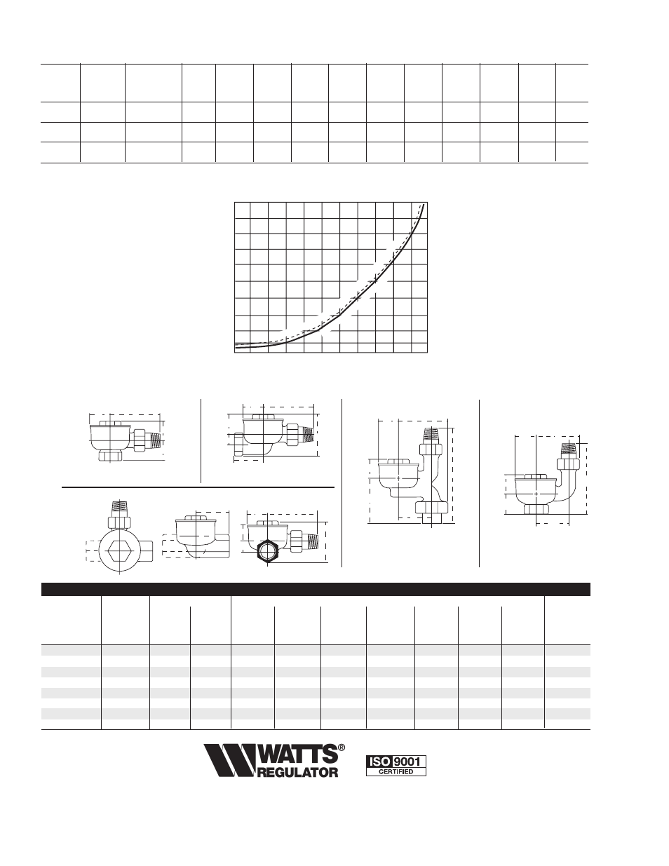
Angle Pattern
1GAP, 3GHAP, 5MGHAP
Straightway Pattern
1GHSW, 3GHSW
Corner Pattern
1GLHC, 1GRHC
- - - LEFT HAND
—— RIGHT HAND
Vertical Pattern
Double Union
1 VGDU
Vertical Pattern
Single Union
1VG
C
G
F
B
D
D
B
E
F
C
G
F
A
C
D
E
G
E
MODEL
PATTERNS
TAPPING
DIMENSIONS
WEIGHT
Male
Inlet
Outlet
Tailpiece
A
B
C
D
E
F
G
in.
mm
in.
mm
in.
mm
in.
mm
in.
mm
in.
mm
in.
mm
in.
mm
in.
mm
lbs.
kgs.
1GAP-1MGAP
Angle
1
⁄
2
15
1
⁄
2
15
2
7
⁄
8
73
1
1
⁄
8
29
1
3
⁄
16
35
1
3
⁄
8
35
–
–
–
–
–
–
1.2
.54
1GRHC-1GLHC
Corner
1
⁄
2
15
1
⁄
2
15
2
7
⁄
8
73
–
–
1
3
⁄
16
35
1
3
⁄
8
35
9
⁄
16
14
2
5
⁄
8
67
1
5
⁄
8
41
1.4
.64
1GSW-1MGSW
Straightway
1
⁄
2
15
1
⁄
2
15
2
7
⁄
8
73
–
–
1
3
⁄
16
35
1
3
⁄
8
35
9
⁄
16
14
2
5
⁄
8
67
1
5
⁄
8
41
1.2
.54
1VG
Vert. S.U.
1
⁄
2
15
1
⁄
2
15
–
–
1
1
⁄
8
29
1
3
⁄
16
35
1
3
⁄
8
35
1
7
⁄
8
48
4
102
2
5
⁄
8
67
1.4
.64
1VGDU
Vert. D.U.
1
⁄
2
15
1
⁄
2
15
–
–
2
9
⁄
16
65
1
3
⁄
16
35
1
3
⁄
8
35
1
7
⁄
8
48
5
3
⁄
8
137
2
3
⁄
4
70
1.7
.77
3GH-3MGH
Angle
3
⁄
4
20
3
⁄
4
20
3
1
⁄
8
79
1
3
⁄
8
35
1
3
⁄
16
35
1
5
⁄
8
41
–
–
–
–
–
–
1.5
.68
3GH-3MGH
Straight
3
⁄
4
20
3
⁄
4
20
3
1
⁄
8
79
–
–
1
3
⁄
16
35
1
9
⁄
16
40
3
⁄
8
10
2
3
⁄
4
70
1
7
⁄
8
48
1.5
.68
5MGH
Angle
1
25
1
25
3
5
⁄
8
92
1
1
⁄
2
38
1
1
⁄
2
38
1
11
⁄
16
43
–
–
–
–
–
–
2.5
1.13
Maximum Trap Capacities - Pounds condensate per hour, MBH, and square feet EDR
Pressure
Tapping
Differential
Model
(NPT)
(psi)
1
⁄
4
1
⁄
2
1
1
1
⁄
2
2
5
10
15
25
50
65
1G
Lbs. Cond
1 MG
1
⁄
2
"
Per Hour*
21.0
29.7
40.9
49.6
58.4
92.4
133.6
162.5
212.0
309.2
357.3
3GH
Lbs. Cond.
3MGH
3
⁄
4
"
Per Hour*
40.8
56.9
81.8
99.3
115.5
182.3
264.7
330.2
436.8
618.4
858.7
Lbs. Cond.
5MGH
1"
Per Hour*
71.8
101.5
143.8
173.7
201.2
319.7
463.9
584.0
688.7
789.5
820.0
* Ratings are in accordance with the recommended standards adopted by the Steam Heating Equipment Manufacturers Association. Select trap directly
from table for the lowest differential that may exist in the system. Traps may be applied directly and no safety factor need by applied.
St
ea
m
Pr
es
su
re
- T
em
pe
ra
tu
re
Cu
rv
e
Bala
nce
d In
tern
al P
re
ss
ur
e -
Te
m
pe
ra
tu
re
Cu
rv
e
of
Th
er
m
os
ta
tic
D
ia
ph
ra
gm
100
120
160
140
180
200
220
240
260
280
300 320
70
60
50
40
30
20
10
0
10
20
Temperature – Degrees F.
Pressure – PSIG
Vacuum – In., HG.
Dimensions — Weights