Specifications cont, How it works, Parts included – Watts LFWDS User Manual
Page 2: Typical installations, Dimensions - weights
Specifications cont.
All connections to the control unit shall be plug in style unique to
the device. Removal of any connector shall result in shut off of
the valve.
The valve shall be resettable upon repair of the system or sys-
tem test.
The Water Detector Shutoff shall be a Watts Series LFWDS.
How It Works:
• The Control Unit, which houses the circuitry, alarm lamp,
audible alarm, alarm silence button, and connector sockets, is
installed on the cold water supply piping to the water heater.
• The exclusive Water Detector Pad lays flat on the floor
(or in a water heater drip pan).
• Upon detection of as little as
1
⁄
16
" of standing water, the
Control Unit initiates the alarm and shutoff sequence.
1. Shuts off the water supply to the water heater. Closes the
cold water supply to the water heater to minimize water
leakage and water damage.
2. Removes the source of power to the water heater. If the
water detected is from the discharge of a temperature and
pressure safety relief valve under emergency conditions,
power to the water heater must be removed immediately.
This protects your home or business against the danger of
explosion.
3. Energizes an audible alarm and remote alarm contacts.
The Series LFWDS has an internal alarm to alert the home-
owner. It also has contacts that can be connected to moni-
tored alarm systems, to provide 24/7 notification to a home
or business security service.
Parts included:
Water Detector Pad
The Water Detector Pad lays
flat on the floor or in a water
heater drip pan. The pad
employs state-of-the-art sens-
ing technology. There are no
terminals to rust or corrode
assuring years of maintenance
free operation.
Power Cutout Module
The Power Cutout Module is
specific to the LFWDS model;
electric, oil fired/spark ignition,
or standing pilot. Standing pilot
units are used to interrupt the
thermocouple, and they are
available in right-hand threaded
and left-hand threaded models.
Water Dam
The rubber Water Dam can be
easily placed around the perim-
eter of the water heater and cut
to the proper length. The dam
can be used for concrete, lino-
leum, tile or other hard surface
flooring.
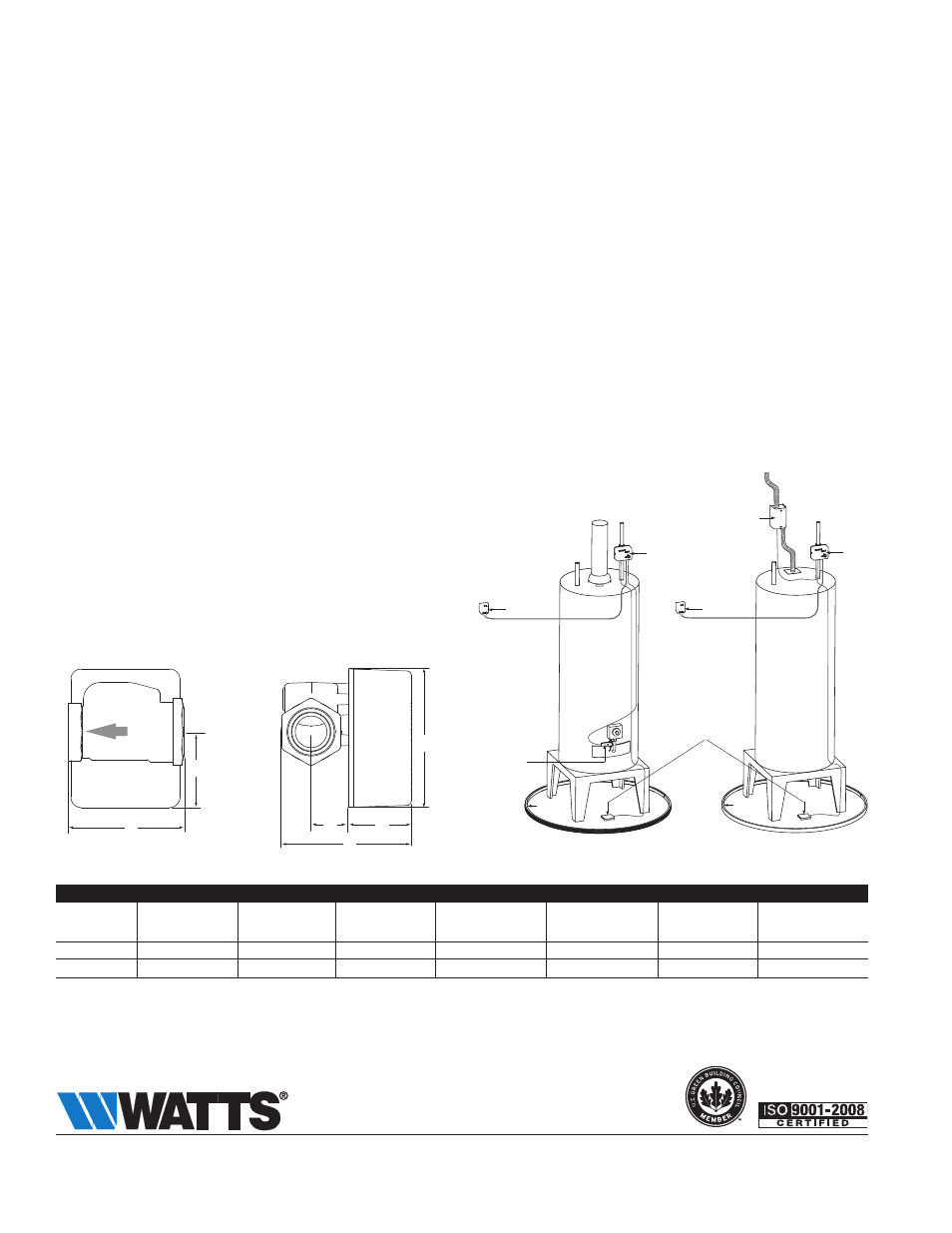
Typical Installations
The FloodSafe
®
Water Detector Shutoff can be installed in new
construction or as an upgrade to existing installations.
Gas Fired Water Heater
Electric Water Heater
Control
Unit
Control
Unit
Power
Supply
Power
Supply
Water
Dam
Water
Dam
Water Detector
Pad
Dimensions - Weights
F
A
B
D
E
C
SizE (DN)
DimENSioNS
WEight
A B C D
E F
in.
mm in.
mm in.
mm in.
mm
in. mm in. mm in.
mm
lbs. kgs.
3
⁄
4
20
3
5
⁄
16
84 4
1
⁄
8
104
3
5
⁄
8
92 1
7
⁄
8
48 2
1
⁄
4
57
15
⁄
16
23 2.0 0.9
1 25
3
7
⁄
16
87 4
1
⁄
8
105
3
7
⁄
8
98 1
7
⁄
8
48 2
1
⁄
4
57
1
1
⁄
8
28 2.1 0.9
Power
Cutout
Module
Power
Cutout
Module
ES-LFWDS 1320
© 2013 Watts
USA: Tel: (978) 688-1811 • Fax: (978) 794-1848 • www.watts.com
Canada: Tel: (905) 332-4090 • Fax: (905) 332-7068 • www.watts.ca
A Watts Water Technologies Company
Control Unit
The Control Unit which houses
the circuitry for the operation of
the valve, contains an interlock-
ing connection for the water
detector pad, the power sup-
ply, remote alarm and power
cutout module.