Materials, Pressure - temperature, Installations – Watts LF800M4FR User Manual
Page 2: Dimensions – weights standards, Approvals, Freeze protection guidelines, Notice
Materials
Springs
Stainless Steel
Bonnet
Celcon
Vent Disc
Silicone Rubber
Disc Holder Float Polypropylene
Check Valve Disc Silicone Rubber
Check Valve Seat Noryl
®
Plastic
Body
Lead Free* Copper Silicon Alloy
Pressure - Temperature
Temperature Range: 33°F to 140° (0.5°C to 60°C)
Maximum Working Pressure: 150psi (10.3 bar)
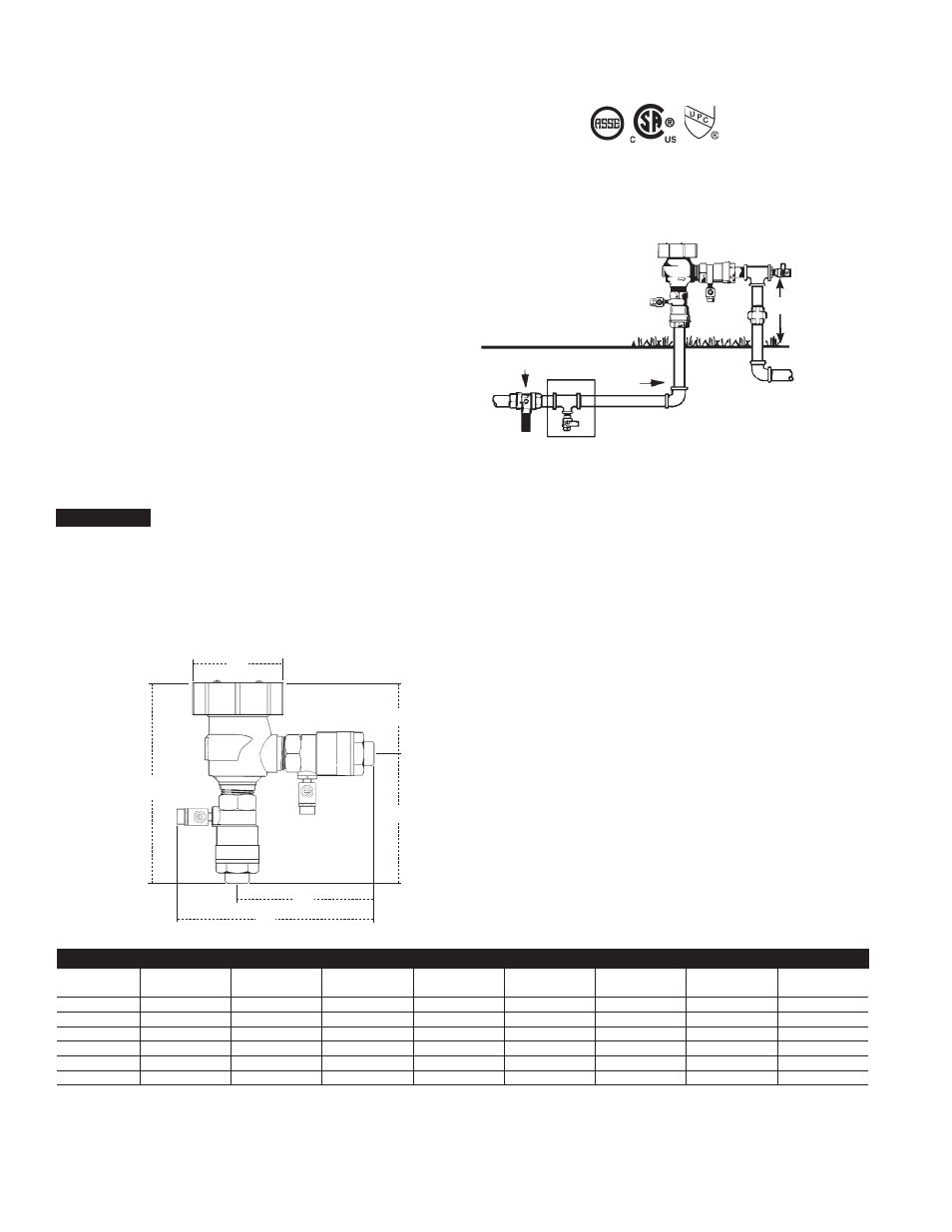
Installations
This valve is designed for installation in a continuous pressure
potable water supply system 12" above the highest point of the
downstream piping. The valve must be installed with the supply
connected to the bottom and in a vertical position. Allow adequate
space for periodic inspection, servicing or testing. The valve should
not be installed in an area where freezing or spillage will cause
damage. Adequate drainage/freeze protection must be provided in
cold weather applications. 1.5psi (.10 bar) must be exerted against
the float spring to seal the float and air inlet. Do not undersize sup-
ply and discharge piping.
Vacuum breakers are not designed, tested or
approved to protect against backpressure backflow or water ham-
mer shock. For protection against backpressure backflow, install
Watts LF009 Reduced Pressure Zone Backflow Preventer. For
Protection against water hammer shock install a Watts Series
LF15 Water Hammer Arrestor utilizing good plumbing practice.
Dimensions – Weights
Standards
ANSI, IAPMO, USC Manual Section 10
Approvals
IAPMO
Approved by the foundation for Cross-Connection Control and
Hydraulic Research at the University of Southern California,
Manual Section 10.
Freeze Protection Guidelines
1. Close main shutoff valve.
2. Open upstream drain, test cocks and isolation
ball valves to depressurize line.
3. Purge with air.
4. Leave test cocks and isolation ball valve handles in 45°
angle to drain ball valves and prevent casting damage.
45°
Union
Outlet Drain
Valve
Flow
Inlet Drain
Main Shutoff Valve
12" Minimum
clearance
above the
highest
point of
downstream
piping.
1020
B64.12
D
C
E
A
G
B
LF800M4FR
Noryl
®
is a registered trademark of SABIC Innovative Plastics™.
moDEl
SizE (DN)
DimENSioNS
WEiGht
A
B
C
D
E
G
in.
mm
in.
mm
in.
mm
in.
mm
in.
mm
in.
mm
in.
mm
lbs.
kg.
LF800M4FR
1
⁄
2
15
6
1
⁄
8
156
6
1
⁄
4
159
2
9
⁄
16
65
3
11
⁄
16
94
3
7
⁄
8
98
2
1
⁄
4
57
4
1.8
LF800M4FR
3
⁄
4
20
6
1
⁄
2
165
6
1
⁄
2
165
2
9
⁄
16
65
3
15
⁄
16
100
4
1
⁄
8
105
2
1
⁄
4
57
4
1.8
LF800M4FR
1
25
7
1
⁄
2
191
7
1
⁄
2
191
2
3
⁄
4
70
4
3
⁄
4
121
4
7
⁄
8
124
3
7
⁄
16
87
6
2.7
LF800M4FR
1
1
⁄
4
32
8
7
⁄
8
225
9
229
3
1
⁄
4
83
5
3
⁄
4
146
6
1
⁄
8
156
5
127
11
5.0
LF800M4FR
1
1
⁄
2
40
9
1
⁄
4
235
9
1
⁄
2
241
3
1
⁄
4
83
6
1
⁄
4
159
6
3
⁄
8
162
5
127
14
6.3
LF800M4FR
2
50
10
5
⁄
8
270
9
5
⁄
8
245
3
1
⁄
4
83
6
3
⁄
8
162
7
178
5
127
19
8.6
NOTICE