2 components and connectors, Figure 1, Components and connectors of the variocell – Metrohm Variocell for Bioscan – 6.5331.1X0 User Manual
Page 9
■■■■■■■■■■■■■■■■■■■■■■
2 Components and connectors
IC Equipment set Variocell for Bioscan
■■■■■■■■
3
2 Components and connectors
Note
The Variocell is supplied fully mounted. Immediately after receipt, check
whether the shipment has arrived complete and without damage by
comparing the delivery note with the list of accessories (see Chapter
6.1, page 15).
1
2
3
4
5
6
7
8
9
10
11
12
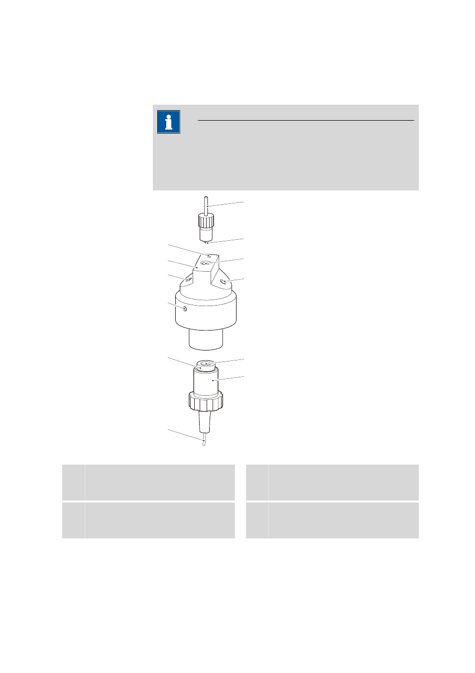
Figure 1
Components and connectors of the Variocell
1
Reference electrode connector
For connecting the black 6.2156.000 elec-
trode cable.
2
Reference electrode
3
Auxiliary electrode
4
Auxiliary electrode connector
For connecting the blue 6.2156.000 elec-
trode cable.