3 instrument display, Instrument display, Figure 3 – Metrohm 895 Professional PVC Thermomat User Manual
Page 16
2.3 Instrument display
■■■■■■■■■■■■■■■■■■■■■■
8
■■■■■■■■
895 Professional PVC Thermomat
2.3
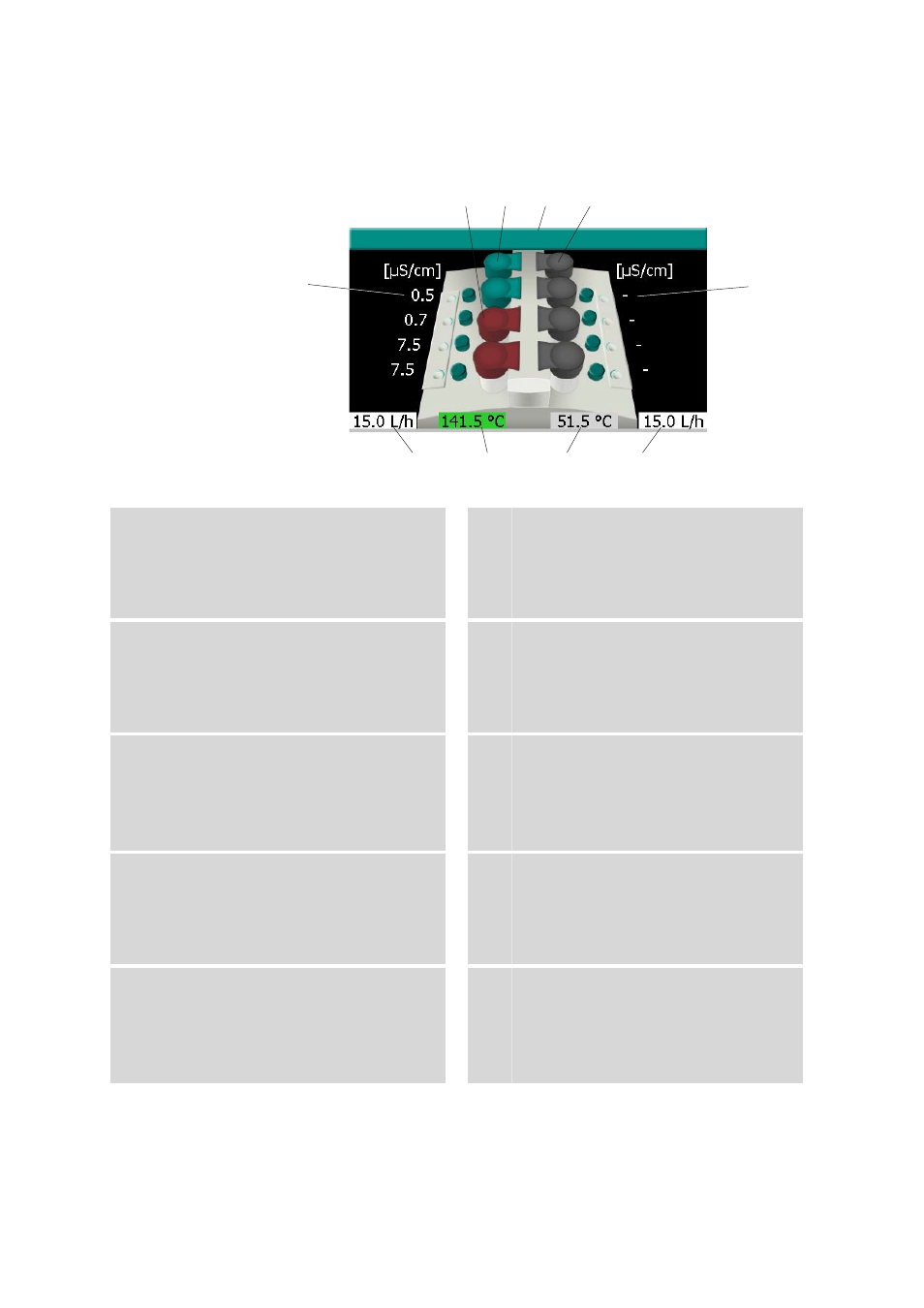
Instrument display
895_1
1 2 3 4
9 8 7 6
10
5
Figure 3
Instrument display
1
Measuring vessel cover red
This measuring position is not available for a
determination (determination is running or
multiple determination has not yet been
completed).
2
Measuring vessel cover green
A determination can be started on this mea-
suring position.
3
Instrument name
The instrument name display corresponds to
the configuration in StabNet.
4
Measuring vessel cover gray
This measuring position is not available for
starting a determination (instrument not
connected to computer or no method loa-
ded).
5
Conductivity display block B
Shows the measured conductivity.
Dash (-) is displayed = Conductivity cannot
be displayed (no sensor connected or no
valid measuring signal).
6
Gas flow display block B
Shows the gas flow measured on block B
(gray background: gas flow switched off;
white background: gas flow switched on).
7
Temperature display block B
Shows the temperature measured on block
B (gray background: heater switched off; red
background: temperature not stable; green
background: temperature stable).
8
Temperature display block A
Shows the temperature measured on block
A (gray background: heater switched off;
red background: temperature not stable;
green background: temperature stable).
9
Gas flow display block A
Shows the gas flow measured on block A
(gray background: gas flow switched off;
white background: gas flow switched on).
10 Conductivity display block A
Shows the measured conductivity.
Dash (-) is displayed = Conductivity cannot
be displayed (no sensor connected or no
valid measuring signal).