Overview – Dulce Systems PRO EX User Manual
Page 6
Page 10
PRO EX Installation and User’s Manual
3. Overview
3.1.
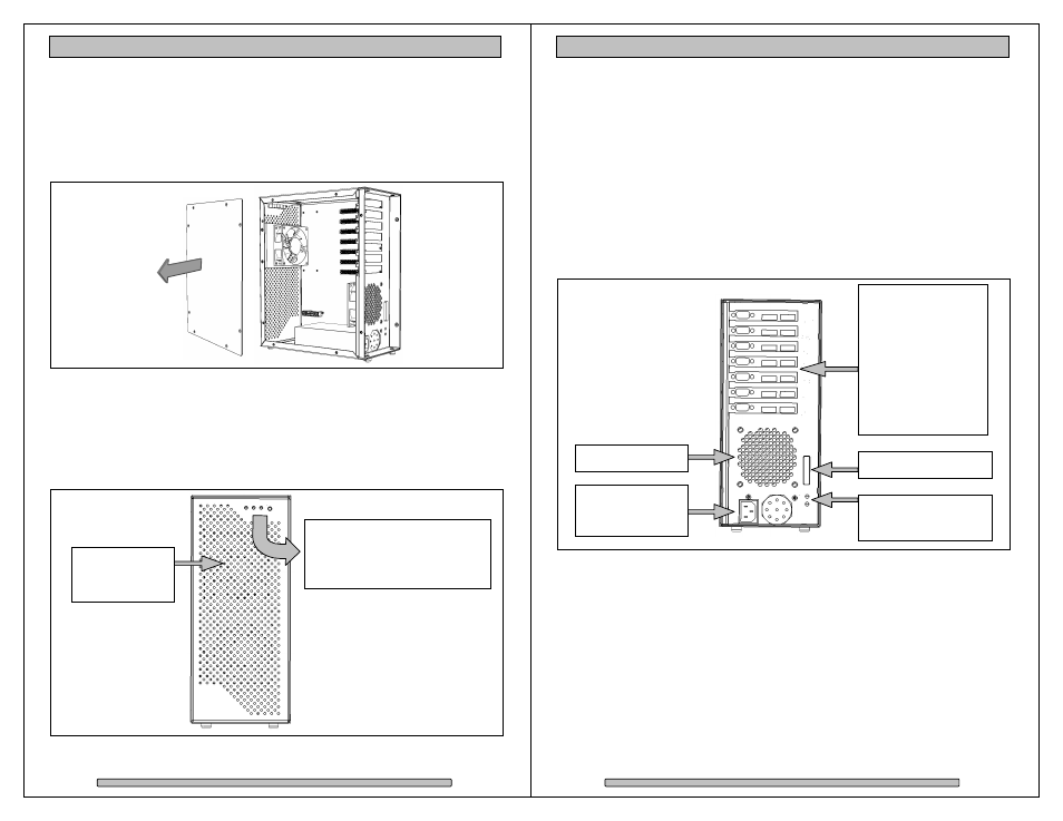
Removing the Cover
The PRO EX expansion slots are accessible by removing the side cover.
Remove the eight Philip screws and remove the cover.
3.2.
Front Indicators and Controls
The PRO EX enclosure has stand alone self-monitoring features. It monitors
temperature and fan continuously. Should the temperature exceed a safe
operating range or the fan spin below a preset minimum, the alarms will be
triggered. A red indicator light will come on plus an audible alarm will sound.
Mute Alarm Button (Green)
Temp Indicator (Green)
Fan Indicator (Green)
Power Indicator (White)
Cooling fan for
add-on cards
behind cover.
Page 11
PRO EX Installation and User’s Manual
3.3.
Rear Indicators and Ports
Uplink Port
Connects to Uplink Host Adapter installed in host computer or
another PRO EX via an x8 Uplink Cable.
Link Indicator
Green when uplink link is established.
Ready Indicator Green when PRO EX is ready for operation.
Power Plug
Power source input. Note there is no power on / off switch. PRO EX
power state is remotely controlled by Uplink Host Adapter and host
computer. Uplink cable must be attached for remote power control to
operate.
Expansion Slots:
Slot A (x4 speed)
Slot B (x4 speed)
Slot C (x4 speed)
Slot D (x4 speed)
Slot E (x8 speed)
Slot F (x8 speed)
Slot G (x8 speed)
(Shown with
slots populated)
Uplink Port.
Link Indicator
Ready Indicator
Enclosure Fan
Power Plug and
Power Supply
Fan