System block diagram – Bird Technologies 4421-110 User Manual
Page 3
Power Meter Model 4421-110
Page 3
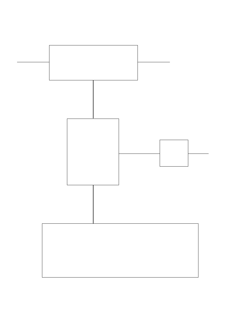
System Block Diagram
Power Sensor
Fiberoptic
Interface
AC Mains
Adapter
Power Meter
50 OHM
50 OHM
Sensor IN
12V DC
Power
Sensor
Fiberoptic
Interface
Signal Source
50 OHM Termination
Sensor Cable
Fiberoptic Cable
220Vac
Refer to safety information in the model 4421 operating instructions prior to installation.
Transmitted traveling waves should always be applied to source input of power sensor.
Applying travelling waves to load port will result in erroneous display.