Replacing the meter, Figure 10 replacing the meter – Bird Technologies 4314B User Manual
Page 37
25
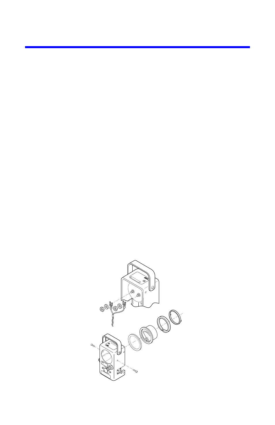
Replacing the Meter
1.
Remove the back cover by unscrewing the four 8-32 Phillips flat head
screws.
Note:
The screws are located two on each side of the meter hous-
ing near the back edge at the top and bottom of the sides.
2.
Loosen the two 8-32 nuts securing the meter leads
3.
Remove the meter leads.
4.
Remove the two 10-32 oval head Phillips screws securing the meter shock
ring.
5.
Pull the meter and shock ring assembly out of the housing from the back.
Note:
If the three rubber shock mount buttons, P/N 4420-098, that
the meter rests on are to be reused, be careful not to lose them. How-
ever, if the replacement shock ring, P/N 4410A261, is to be used
instead, the buttons may be discarded.
6.
Remove the meter retaining ring and shock mount from the meter.
7.
Replace the meter.
Note:
If the replacement shock ring is used, peel off the white strip
covering the adhesive backing. Carefully adhere the shock ring to the
front bezel flange.
Note:
Be sure to observe the polarity when replacing the leads to the
meter, black to negative, red to positive.
8.
Zero adjust the meter.
Figure 10 Replacing the Meter
Thruline
WAT
TMETER
MODEL
4410A
SERIAL
NUMBER
IMPEDANCE
ELECTRONIC
CORPORA
TION
CLEVELAND
(SOLON),
OHIO
MUL
TIPY
SWIT
CH
SETTING
BY
ELEMENT
FACT
OR
!
DA
NGER
RF
VO
LTA
GE
KE
EP
ELE
ME
NT
IN
LIN
E
SO
CK
ET
DU
RIN
G
OP
ER
ATIO
N
OFF
O.1
0.3
WA
TT
S
TH
RULIN
E
Thruline
WA
TTMETER
MODEL
4314B
SERIAL
NUMBER
XXX
BIRD
ELECTRONIC
CORPORA
TION
CLEVELAND
(SOLON),
OHIO
+