Rejection notch, Checking the rejection notch – Bird Technologies 15-88-01 User Manual
Page 7
TX RX Systems Inc. Manual 7-9150-2 07/19/07 Page 3
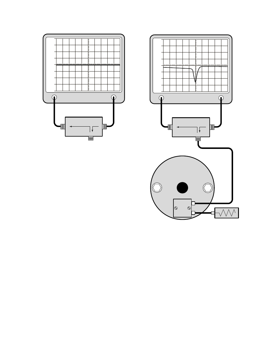
7. Connect the "load" port on the RLB to one of
the input /output ports and make sure the
remaining port is connected to a 50 ohm load;
refer to Figure 4. The display will now present
the return loss curve for the 4" Vari-Notch filter
being measured. The passband is that fre-
quency range over which the return loss is
15 dB or greater.
The resonant frequency is adjusted by using the
tuning rod, which is a sliding adjustment (invar rod)
that rapidly tunes the response curve across the
frequency range of the filter. Resonant frequency is
increased by pulling the rod out of the cavity and is
decreased by pushing the rod into the cavity. For
ease in making adjustments, rotate and slide the
rod while gently tapping on it with a screwdriver or
other small tool. This will break the surface tension
on the probe contact fingers and allow smoother
movement of the tuning rod.
Once the desired response is obtained using the
tuning rod, it is "locked" into place by tightening the
1/4" shaft lock nut. Failure to lock the tuning rod
will cause a loss of temperature compensation and
detuning of the cavity.
REJECTION NOTCH
The rejection notch will track with the tuning of the
passband and therefore should be the last adjust-
ment made to the 4" Vari-Notch filter. The rejection
notch is adjusted by changing the amount of
capacitance in the loop assembly. The capacitor is
a variable tubular-piston type.
Checking the rejection notch
1. The rejection notch is checked by connecting
the tracking generator to the input of the cavity
filter while the spectrum analyzer is connected
to the output, as illustrated in Figure 5.
2. Insure that the IFR A-7550 menu's are set as
follows:
DISPLAY - line
MODE - live
FILTER - none
SETUP - 50 ohm/dBm/gen1.
LOAD
REFLECTED
SOURCE
Analyzer
Input
Generate
Output
+30
+40
+20
+10
0
-10
-20
-30
-40
RLB - 150 Bridge
Figure 3: Setting the return loss reference.
LOAD
REFLECTED
SOURCE
Analyzer
Input
Generate
Output
+30
+40
+20
+10
0
-10
-20
-30
-40
RLB - 150 Bridge
50 Ohm Load
4" Diameter
Vari-Notch
Filter
Figure 4: Checking the passband.