Figure 4 thermoswitch assembly, Connecting rf power, Qc” connector coupling – Bird Technologies 8860 Series User Manual
Page 17: 30 coupling, Swivel flanged coupling, S 7, 9, 11
7
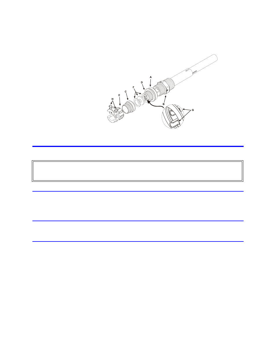
Figure 4 Thermoswitch Assembly
Connecting RF Power
After installing the load, the RF transmission line can be attached using standard coaxial line coupling kits.
“QC” Connector Coupling
Use 50 ohm coaxial cable such as RG-218/U or -220/U (-17A or -19A), appropriate for the frequency and power level
of operation.
Use a cable connector which will mate with the one on the load.
13-30 Coupling
Use 50 ohm coaxial cable such as RG-8A/U, RG-9U, RG-213/U, or equivalent with a male 13-30 plug.
Swivel Flanged Coupling
Note: To couple the swivel flange with a flanged RF transmission line, use an
appropriate coupling kit. Refer to Figure 5.
1.
Insert the center bullet.
2.
Push it in until it is fully seated.
3.
Connect the coaxial input in a straight line.
4.
Push carefully on the center conductor to close.
Note: The swivel flange on the load makes connection independent of the ori-
entation of the fixed flange on the coaxial input outer conductor.
5.
Insert the bolt sets.
6.
Tighten evenly all around to transmission line manufacturer’s recommended torque.
Note: Use all of the bolts.
WARNING
Never attempt to connect or disconnect RF equipment from the transmission line while RF power is being
applied. Leaking RF energy is a potential health hazard.