Burnham LEDV SERIES User Manual
Page 13
13
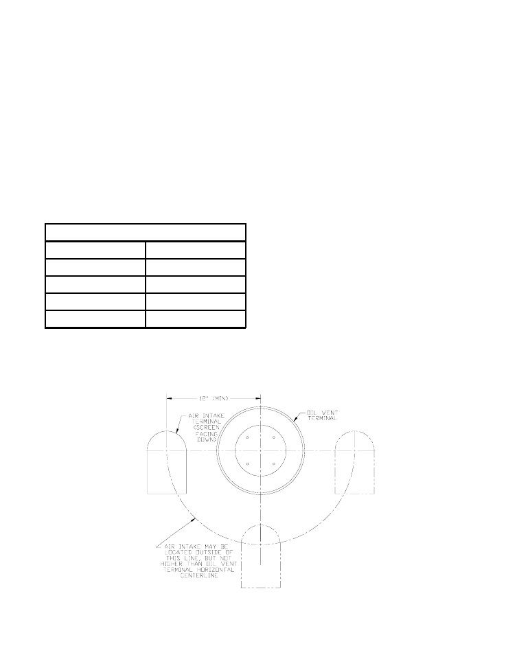
6. Intake Terminal Location (Direct Vent only) - Locate
Air Intake Terminal not less than 12 inches to the
left, right, or bottom of the vent terminal. Do not
locate air intake terminal above vent terminal. Intake
terminal must be at least 12 inches above grade plus
snow accumulation. See Figure 9.
7. The LEDV must be vented with 4" Z-Flex Direct
Oil™ Vent. 20 feet is the maximum vent length
allowed. The vent pipe is available in 5, 10, 15, and
20 foot lengths. Table 1 lists vent part numbers.
Figure 9: Intake Terminal Location
Components of this kit are listed in the Repair Parts
Section of this manual.
B.
Vent Installation (Direct Vent and Side-Wall Vent)
1. Install Vent Terminal. See Figure 10.
a. After determining the location from previous
Section, cut an opening in the wall for the vent
terminal.
•
Combustible wall: 8 inches diameter hole is
required to maintain a 1 inch clearance to
combustible materials.
•
Non-combustible wall: 6½ inches diameter
hole is required.
b. Secure trim plate to outside wall.
c. Insert the vent terminal through the opening
until the stop bead rest against the trim plate.
d. Slide the inside trim plate assembly (fitted with
gear clamp) onto the terminal pipe.
Table 1: Vent Pipe Part Numbers
4" Direct Oil™ Vent Pipe
Pipe Length
Burnham Part No.
5 Ft.
8113302
10 Ft.
8113303
15 Ft.
8113304
20 Ft.
8113305
8. The vent system must be completed with the Direct
Oil™ Vent Kit, which is shipped with the boiler.