Installation – Bird Technologies 89-86A-02-18 User Manual
Page 2
TX RX Systems Inc. Manual 7-9434-2 07/15/09 Page 2
INSTALLATION
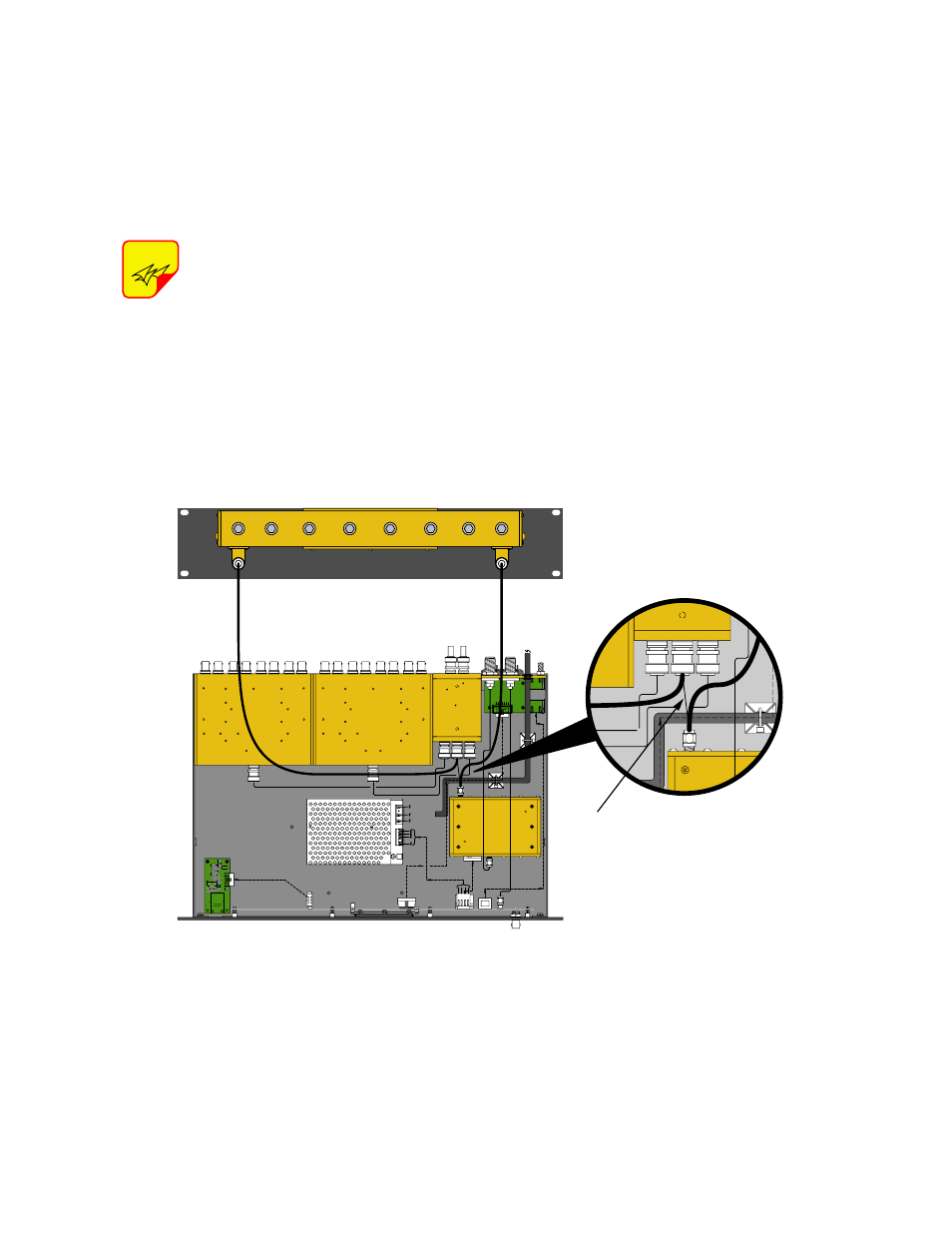
Figure 2 shows the cable interconnections that are
required between the filter and the TTA. To install
the optional narrowband filter in your TTA system
perform the following steps;
Power to the MCU should be turned
off during installation of the preselec-
tor.
1) On the MCU, disconnect the existing cable that
runs between the output of the distribution
amplifier and the input of the 4-way divider, see
Figure 2. Use a 5/16” open-end wrench to
loosen the SMA connector on the amplifier end
of the cable. The end of the cable connected to
the 4-way uses a BNC connector. You may wish
to save the cable for future re-use if you ever
decide to remove the optional filter from your
TTA system.
2) With the supplied screws, mount the preselec-
tor panel into the 19-inch rack above the MCU.
3) Locate a new cable assembly with “SMA” and
“N” male connectors. Connect the “SMA” end of
the cable to the output port of the amplifier
assembly. Connect the “N” end of the cable to
the output connector on the preselector.
4) Locate a new cable assembly with “BNC” and
“N” male connectors. Connect the “BNC” end of
the cable to the RF input connector on the 4-
way divider. Connect the “N” end of the cable to
the output connector on the preselector.
NOTE
Remove Existing
Cable 3-19152
Figure 2: Connecting the narrowband preselector to the TTA.