Bendix Commercial Vehicle Systems EverSure Spring Brake with No Touch Technology User Manual
Page 3
3
The diaphragm is held between the adapter base and non-
pressure plate by a two piece clamp ring.
Different size brake chambers are identified by numbers,
which specify the effective area of a diaphragm. For
example, a Type 30/30 Spring Brake has 30 square inches
of effective area on each diaphragm.
The standard diaphragm material is a compound of natural
rubber with a fabric interior of nylon.
WARNING!
• Spring brake chambers contain a loaded
compression spring. Property damage, serious
injury or death may occur if instructions are not
followed completely.
• When performing any maintenance on the spring
brakes, make sure to block the wheels to prevent
vehicle rollaway.
• DO NOT SERVICE A SPRING BRAKE CHAMBER
IF IT HAS STRUCTURAL DAMAGE OF ANY KIND.
Replace the complete assembly. Dismount a
damaged spring brake by first cutting the service
push rod with an acetylene torch to relieve any
force it might have.
• Do not strike any part of a spring brake chamber
for any reason. This may cause structural damage.
• Be careful not to drop a spring brake chamber at
any time. If dropped, inspect for signs of structural
damage. Replace complete assembly if damaged.
• Spring brake chambers cannot have the emergency
diaphragm replaced. Replace the whole spring
brake chamber.
• Always work from the side of the spring brake
chamber. Never work from the front or back.
3. PREVENTIVE MAINTENANCE
Important: Review the warranty policy before performing
any intrusive maintenance procedures. An extended
warranty may be voided if intrusive maintenance is
performed during this period.
Because no two vehicles operate under identical conditions,
maintenance intervals will vary. Experience is a valuable
guide in determining the best maintenance interval for a
vehicle.
3.1. EVERY 300 OPERATING HOURS,
8,000 MILES, OR ONE (1) MONTH:
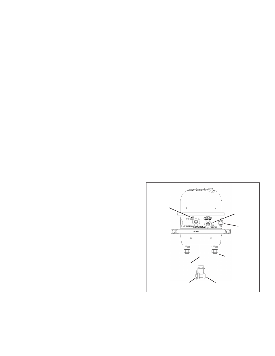
3.1.1. See Figure 2. Check push rod travel and adjust
travel at the slack adjuster if needed (only where manual
slack adjusters are used). Push rod travel should be as
short as possible without the brakes dragging (consult
the manufacturer’s installation instructions for the slack
adjuster. Excessive push rod travel reduces braking
efficiency, shortens diaphragm life, gives slow braking
response, and wastes air.
3.1.2. Check push-rod-to-slack-adjuster alignment from
release to full stroke position to be sure the push rod
moves out and returns properly without binding at the non-
pressure plate hole or with other structures. Also, check
the angle formed by the slack adjuster arm and push rod.
It should be greater than 90 degrees when the chamber
is in the released position and approach 90 degrees at
maximum readjustment stroke.
3.1.3. Check tightness of mounting nuts. Torque on the
non-pressure plate mounting nuts should be 133-155 ft/
lbs.
3.1.4. Check cotter pins to ensure they are in place.
3.1.5. Check all hoses and lines. They should be secure
and in good condition with sufficient length to allow for axle
movement.
3.2. EVERY 3,600 OPERATING HOURS,
100,000 MILES OR ONE (1) YEAR:
3.2.1. Carefully inspect all metal parts for cracks, distortion
or damage.
3.2.2. Perform the Leakage Test (4.2). As necessary,
install a new diaphragm or any other parts if they are worn
or deteriorated. All diaphragm sealing surfaces should
be smooth and clean. Perform the steps outlined in
"12. Replacing the Service Diaphragm". When the service
diaphragm, service return spring, or both are replaced, they
should also be replaced in the corresponding chamber on
the same axle.
RELEASE
TOOL
SIDE
PARKING/
EMERGENCY
PORT
SERVICE
PORT
MOUNTING NUT
COTTER PIN
YOKE
SERVICE
PUSH ROD
FIGURE 2 - SPRING BRAKE EXTERNAL VIEW