Bendix Commercial Vehicle Systems Vertical and Lateral Alignment of Bendix Radar Sensors User Manual
Page 5
5
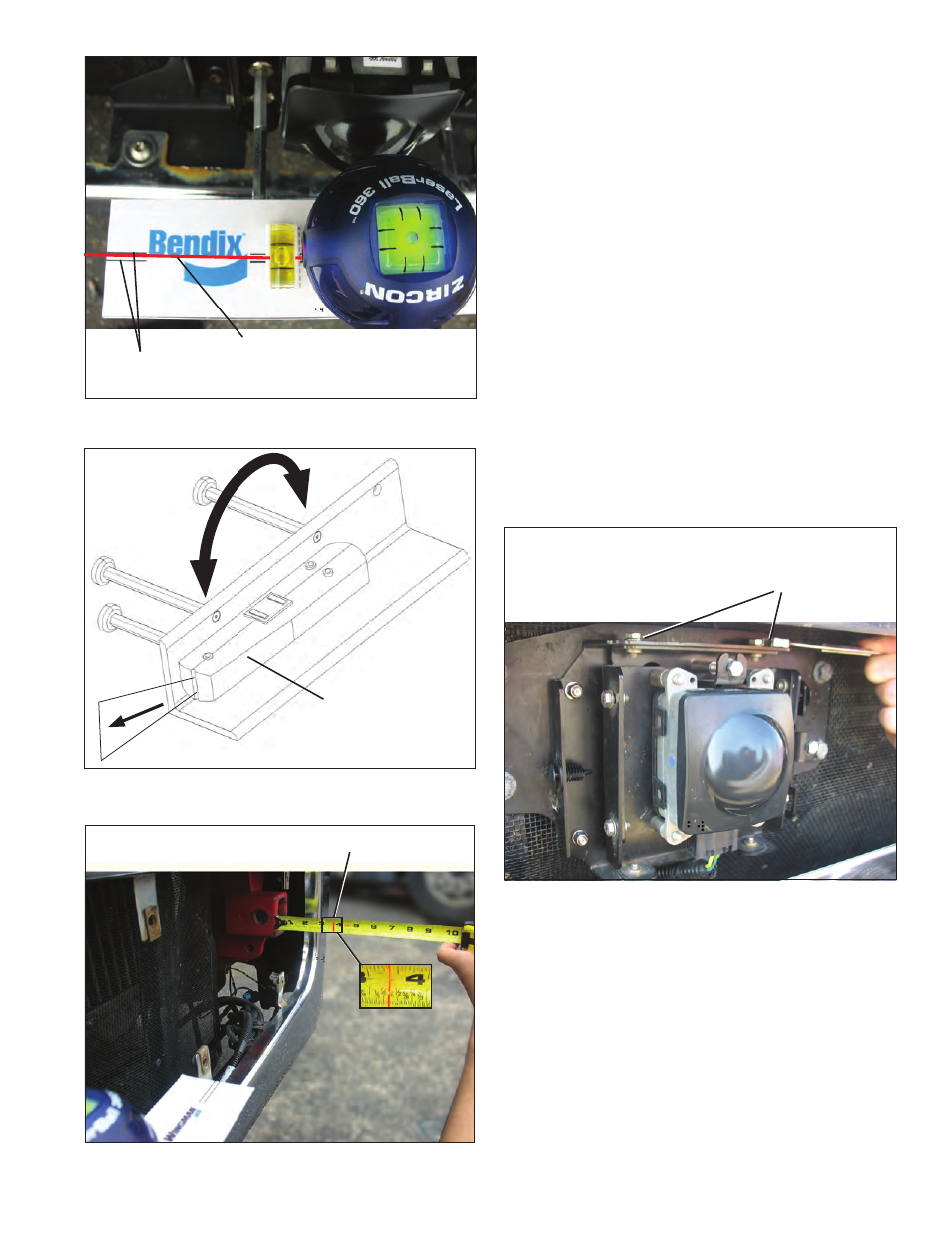
FIGURE 33 - POSITIONING THE LASER LEVEL (KITS
K041451 OR K041227)
Laser Light
Beam
Beam
Reference Lines
FIGURE 34 - USING THE LATERAL ALIGNMENT LEVEL
(KIT K065284)
Lateral Alignment
Laser
Laser
Light Beam
The Whole
Tool is
Reversed for
the Second
Measurement
FIGURE 35 - LATERAL ALIGNMENT VERIFICATION
Laser Light Line
NOTE: The lateral alignment also can be checked with
Bendix ACom
®
Diagnostics (version 6.3 or higher). A
value between -0.8° and 0.8 ° is acceptable and the
system should operate normally. A value between
-0.8° to -1.3° OR 0.8° to 1.3° means the radar sensor is
misaligned and system performance will be degraded.
The service technician should align the radar sensor
using the procedures noted in this section.
If the value is less than (<) -1.3°, or greater than
(>) 1.3°, the system will typically issue a Diagnostic
Trouble Code. The service technician should align
the radar sensor laterally. A positive value means the
radar sensor should be aligned toward the driver side.
A negative value means the radar sensor should be
aligned towards the passenger side. The vehicle must
be driven at least 20 miles between adjustments. See
“Alignment Value” in Figure 17.
6.10 LATERAL ADJUSTMENT PROCEDURE
NOTE: Complete these steps only if a vertical adjustment
is necessary.
1. Loosen the four lateral position screws. DO NOT fully
remove them. See Figure 36.
Four Lateral Position Screws
[Two (2) on the top and two (2) on the bottom]
Loosen - Do Not Remove
FIGURE 36 - LATERAL POSITION SCREWS