Bendix Commercial Vehicle Systems Vertical and Lateral Alignment of Bendix Radar Sensors User Manual
Page 4
4
6.08 RADAR SENSOR VERTICAL
ALIGNMENT ADJUSTMENT PROCEDURE
NOTE: Complete these steps only if a vertical adjustment
is necessary.
Tools needed:
7 mm box wrench and Bendix
®
alignment tool.
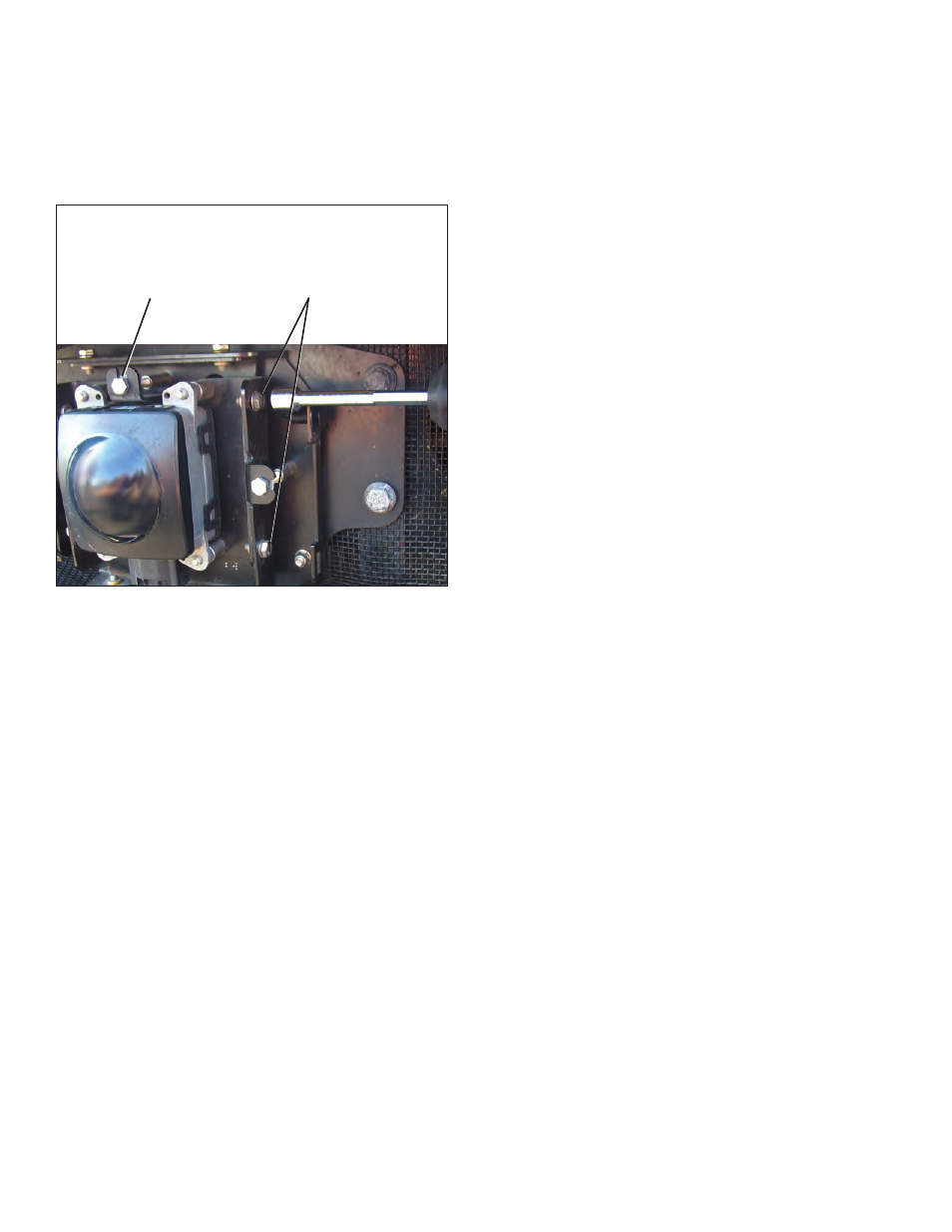
4 Vertical Position
Screws
(2 per side)
Loosen - Do Not
Remove
Vertical
Adjustment
Screw
FIGURE 32 - VERTICAL ADJUSTMENT (NOTE THIS IMAGE
DOES NOT SHOW THE ALIGNMENT TOOL INSTALLED)
1. Be sure the vehicle is prepared as shown in Sections
6.07.1-3.
2. With the Bendix alignment tool still in place, loosen the
four vertical position screws. DO NOT remove these
screws. See Figure 31. During the adjustment, turn the
vertical alignment screw clockwise or counterclockwise
depending on the vertical direction (up or down)
needed. Clockwise aligns the radar sensor up and
counterclockwise moves the radar sensor down.
3.
Where the original tool is being used: (kits K041451
or K041227)
In cases where a digital inclinometer is not being used,
the adjustment should be made until the bubble is just
touching the line closest to the vehicle (See Figure 31.)
4.
Where a digital inclinometer is being used:
Adjust the vertical adjustment screw until the digital
inclinometer shows that the alignment tool is between
-0.5° and -0.7° (downward) when measured by an
inclinometer set to zero on the vehicle’s frame. (See
Figure 29.)
5. Re-tighten the four vertical position screws to hold
desired alignment in place.
6. Re-check the vertical alignment after tightening the four
vertical position screws.
Note: The alignment process shown here is for Bendix
alignment brackets. For other brackets, similar alignment
steps will be needed; consult the vehicle manual for full
instructions.
6.09 CHECK THE RADAR SENSOR
LATERAL ALIGNMENT
See Section 6.06 for available Bendix
®
Alignment Tools.
Tools needed: 7 mm box wrench, Bendix
®
alignment
tool and a tape measure.
1. Park the vehicle on a flat, level surface. The vertical
alignment must be checked and adjusted, if needed,
before the lateral adjustment can be made.
2. Remove the cover as shown previously in Section 6.05:
Cover Removal.
3. Position the alignment tool over the radar sensor so that
it straddles the radar sensor. Attach the alignment tool
to the bracket / radar sensor assembly with its magnet
attachments. See Figures 33 and 34.
4. Activate the lateral alignment laser light “on” switch.
For kits K041451 or K041227, position and place it in
its cradle, making sure it is sitting level, and align the
laser beam between the reference lines on the Bendix
alignment tool left or right. See Figure 32.
For kit K065284, place the tool into postion for the first
measurement. (The tool will be reversed when the
second measurement is made.)
5. Using a ruler or tape measure, measure the distance
from a symmetrical vehicle point (such as the tow
hooks) to the laser light line. Record this measurement.
See Figure 35.
NOTE: The technician must be extremely careful
during the laser positioning process to double-check
the values measured on each side of the truck. Be
sure to check back and forth for each side of the radar
sensor several times to ensure accuracy.
6. Repeat the same process for the opposite side and
measure the reference distance to the laser line.
For tool K042452, the blue laser level is rotated 180
degrees, and for tool K065284, the whole tool is
reversed so that the laser light points to the other side
of the vehicle.
7. Compare the left and right distance measurements.
A properly aligned radar sensor will have the same
measurement from side to side. If these two dimensions
are within 1/8" (3 mm), no alignment is necessary. If
not, follow the instructions in Section 6.10: Lateral
Adjustment Procedure.