Bendix Commercial Vehicle Systems Vertical and Lateral Alignment of Bendix Radar Sensors User Manual
Page 3
3
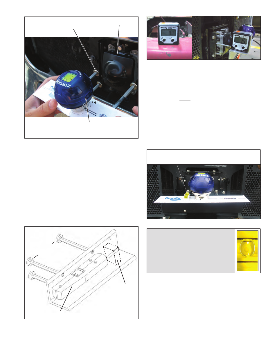
Magnetic
Attachments
Lateral Alignment
Laser Level
Radar Sensor
FIGURE 27 - ATTACHING THE ALIGNMENT TOOL (SHOWS
TOOL K041451 OR K041227)
6.07.5
Check the vertical Alignment.
Using the standard tool K065284. With the air
suspension charged and set to “level”, calibrate (“zero”)
the inclinometer on a horizontal section of the frame rail.
Follow the manufacturer’s instructions (typically digital
inclinometers have a “SET” button for this purpose).
Check the alignment with the alignment tool in position
so that it straddles the radar sensor. Verify that the
radar alignment is within the range of -0.5° to -2.0°
(downward) when measured by an inclinometer set to
zero on the vehicle’s frame. If the sensor is not aligned
correctly, follow the instructions in section 6.08.
Lateral Alignment Laser
Typical Location
for Digital
Inclinometer
(Preferred
Method)
Magnetic
Attachments (3)
FIGURE 28 - VERTICAL ALIGNMENT TOOL (K065284)
FIGURE 29 - INCLINOMETER
6.07.6
If you have the original design of alignment
tool K041451 or K041227 (See Figure 26):
Where a digital inclinometer is available — or if a flat,
level location is not available (in which case a digital
inclinometer must be used) — do not use the bubble
level. Verify that the ACB sensor alignment is within
the range of -0.5° to -2.0° (downward) when measured
by an inclinometer set to zero on the vehicle’s frame.
Where the bubble-level may be used, verify that the
bubble just touches the line nearest the vehicle. This
shows that an incline of approximately one half of a
degree downward has been set. See Figure 31.
Vertical Alignment
Bubble Level
FIGURE 30 - VERTICAL ALIGNMENT BUBBLE LEVEL
Ideal bubble position - just touching the
line nearest to the vehicle.
FIGURE 31 - USING THE BUBBLE POSITION TO CHECK
THE VERTICAL ALIGNMENT (VEHICLE ON LEVEL GROUND)
If the sensor is not aligned correctly, follow the
instructions in section 6.0.8