Bendix Commercial Vehicle Systems AD-IS EVERFLOW ASSEMBLY User Manual
Page 8
8
CLEANING & INSPECTION
Consult the service data sheet for the dryer used in your
AD-IS
®
EverFlow
™
assembly. The service data sheet
contains information useful for maintenance and service
of the air dryers.
1. Use a suitable solvent to clean all metal parts, and
use a cotton swab to clean the bore (Note: Do not use
abrasives or tools to clean the bore: any scratches
caused may necessitate replacing the AD-IS
®
air
dryer.) Superfi cial external corrosion and/or pitting is
acceptable.
2. Clean the o-rings with a clean dry cloth. Do not use
solvents.
3. Inspect for physical damage to the bore and the check
valve seat. If the bore is damaged (by scratches etc.
that would prevent delivery check valve from seating),
replace the AD-IS
®
air dryer.
4. Inspect the delivery check valve, o-rings, etc. for wear
or damage. Replace if necessary using the check valve
replacement kit available at authorized Bendix parts
outlets.
5. Inspect all air line fi ttings for corrosion and replace as
necessary.
Guidelines outlined on pages 5-6 in this document. Also,
always depressurize the air dryer purge reservoir before
servicing the air dryer.
This procedure does not require removal of the AD-IS
®
air
dryer from the vehicle.
1. Remove the line from governor and mark for easy
reinstallation.
2. Remove the bolts attaching the governor to the AD-IS
®
air dryer and retain for reassembly.
3. Remove the governor from the air dryer. Be aware that
a short puff of trapped air may vent when the governor is
removed. Retain the governor gasket for reassembly if
a new governor gasket is not available. Remove and
retain the o-ring from the adapter.
4. The spring/delivery check valve can now be removed.
A second delivery check valve is located in the dryer
without a governor. This check valve is located behind a
hex head plug near the control line from the EverFlow
™
module to the air dryer. Carefully remove the hex plug
and follow the instructions that follow.
5. Remove and retain the o-ring from check valve body.
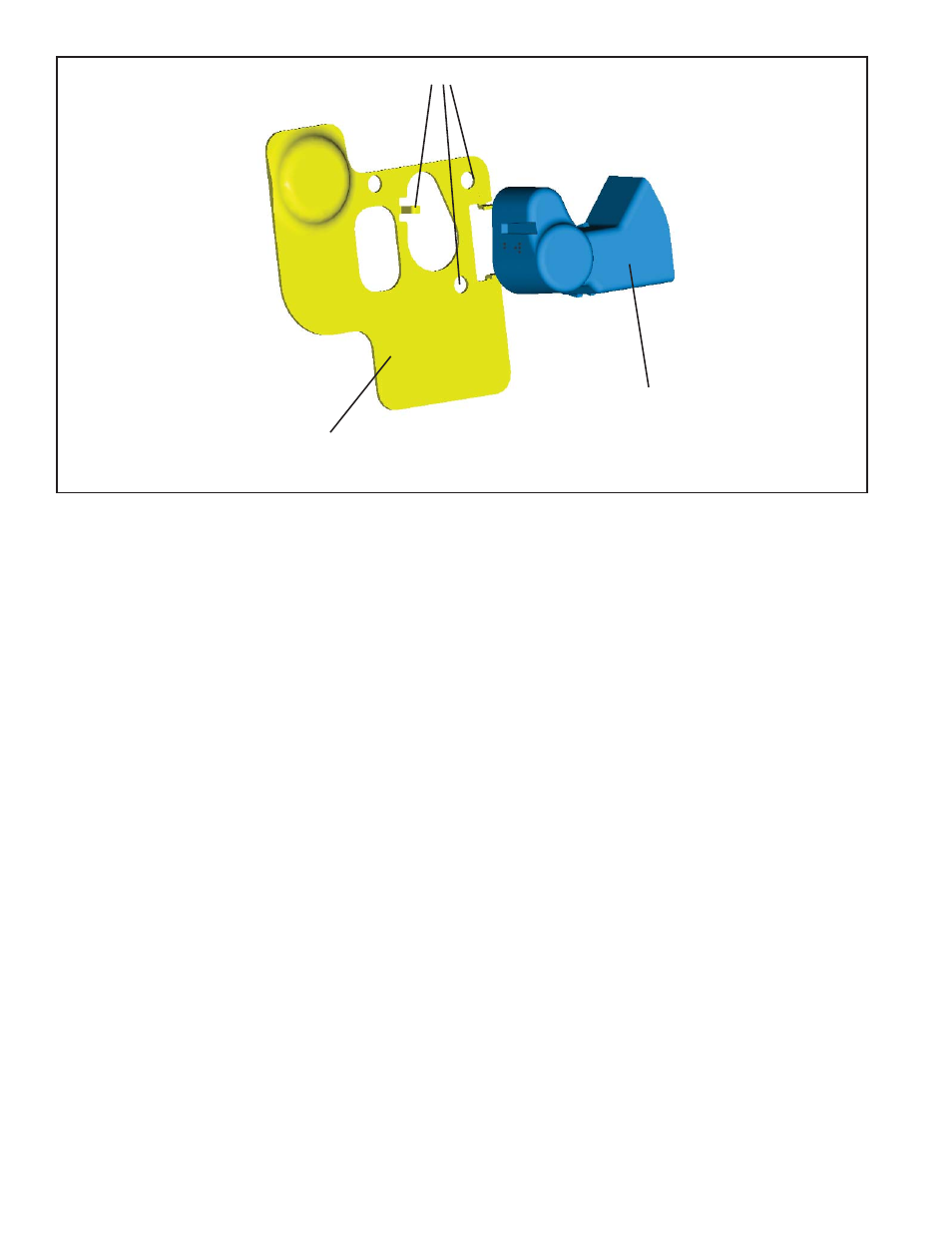
FIGURE 5 - SPLASH SHIELD BRACKET AND COVER - (EXPLODED VIEW)
SPLASH
SHIELD
BRACKET
SPLASH
SHIELD
COVER
LOCK TABS