Bendix Commercial Vehicle Systems AD-IS EVERFLOW ASSEMBLY User Manual
Page 3
3
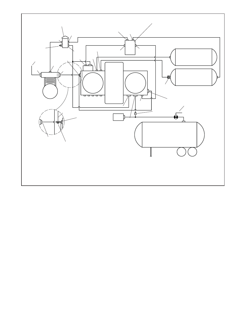
FIGURE 2 - AD-IS
®
AIR DRYER SYSTEM SCHEMATIC
charge cycle until the air brake system pressure builds
to the governor cut-out setting of approximately 130 p.s.i.
When air brake system pressure reaches the cut-out setting
of the governor, the governor unloads the compressor
and the electronic module sends a signal to one of the air
dryers to purge. The governor unloads the compressor by
allowing air pressure to fi ll the line leading to the compressor
unloader mechanism - causing the delivery of compressed
air to the AD-IS
®
EverFlow
™
assembly to be suspended.
Similarly, the governor also supplies air pressure to the
EverFlow
™
electronic module. The electronic module uses
this signal to determine the volume of air into the brake
system. If the volume is normal, the electronic module
sends a signal to the control port on the proper dryer. If the
volume is high, the electronic module switches the dryers
every 30 seconds until the air volume returns to normal.
The air dryer purge piston moves down in response to a
pneumatic signal from the EverFlow
™
electronic module,
causing the purge valve to open to the atmosphere and
Air then fl ows into the desiccant drying bed and becomes
progressively drier as water vapor adheres to the desiccant
material in a process known as “ADSORPTION.” Dry air
exits the desiccant cartridge through the delivery check
valve and also through an orifi ce into the purge reservoir.
The delivery check valve opens, supplying air to pressurize
the air brake system. The purge reservoir stores air that
will be used to reactivate the desiccant during the purge
cycle.
The air dryer will remain in the charge cycle until the air
brake system pressure builds to approximately 85 p.s.i. At
85 p.s.i. the EverFlow
™
electronic module is actuated and
begins the purge cycle. When the air pressure reaches
approximately 106 psi, the pressure protection valves
will open and air will be supplied to the primary reservoir,
secondary reservoir or other accessories. If the pressure
protection valves are preset to different values the valves
will open in order of lowest setting to highest setting when
charging a fl at system. The air dryer will remain in the
Note:
The AD-IS
®
air dryer purge piston has a purge control channel
drain. This allows any condensation in this area to fl ow past
a diaphragm in the top of the purge piston and out through a
channel in the middle of the central bolt of the purge assembly
to be drained. During the purge cycle this drain is closed.
Bulk Tanker
Secondary
Reservoir
Primary
Reservoir
CTI System
Pressure
Protection Valve
(Optional)
IN
CON
OUT
From
Engine
CON
RES
CON
AD-IS
®
EFM
Schrader
Valve
CON
RES
CON
GOV
3/8"
1/2"
1/2"
1/4"
CON
Bulk Offl oad CTI
Dryer OUT
Check
Valve
Supply
IN
SEC
PRI
Supply
IN
CON
Manual Valve
Accessories
Compressor
EverFlow
™
Module
Governor
Compressor
OUT
CON
EverFlow
™
IN
Discharge Line
Unloader Valve