Sc-pr, Valve description, Valve operation – Bendix Commercial Vehicle Systems AD-SP SYSTEM PURGE AIR DRYER 10/04 User Manual
Page 5
5
air to flow through the purge mechanism. Dry air for the
brake system enters the purge control mechanism through
an air channel located in the delivery port, before the delivery
single check valve. It flows through the mechanism and
exits a purge orifice; its pressure is lowered and its volume
increased. The flow of dry air through the drying bed
reactivates the desiccant material by removing the water
vapor adhering to it.
Dry, brake system air will continue to flow through the
desiccant bed until the purge mechanism senses that the
brake system pressure has dropped between 8 - 14 psi
below what it “remembered” as being high (governor cut
out). For example: If governor cutout pressure was 120 psi
the purge mechanism will use air from the supply and front
axle reservoirs until it detects that pressure has dropped to
between 112 - 106 psi. System pressure will be reduced in
the supply and secondary (front axle) reservoirs only. The
primary or rear axle service reservoir will retain governor
cutout pressure (in the example, 120 psi). The purge cycle
and re-activation of the desiccant drying bed along with the
resulting pressure reduction takes place in approximately
15 - 20 seconds.
Once the purge cycle is complete, the purge control
mechanism closes and no further reduction of system
pressure should occur. The air dryer is ready for the next
charge cycle to begin.
The purge valve will remain open and the turbo cut-off valve
closed after the purge cycle is complete and neither will
change position until air brake system pressure is reduced
to governor cut-in pressure and the Charge Cycle begins.
SC-PR
™
VALVE DESCRIPTION
The SC-PR
™
single check protection valve, combines a
single check valve and a pressure protection valve in a single
assembly. Its primary use is in conjunction with the Bendix
®
AD-SP
™
air dryer and is installed in the front axle
(secondary) service reservoir in place of a standard single
check valve.
The SC-PR
™
valve allows the AD-SP
™
air dryer to draw air
pressure from the front axle service reservoir during the purge
cycle. It also protects the air pressure in the front axle
service reservoir, in the event of a compressor, supply, or
rear axle reservoir failure, or malfunction of the AD-SP
™
air
dryer purge control mechanism.
The SC-PR
™
valve is intended for direct mounting to the
service reservoir. Both SC-PR
™
valve air connections are
1/2 inch pipe thread and each is identified with cast,
embossed letters for ease of identification and installation.
The letter identifications and connections to the air system
are shown below for reference.
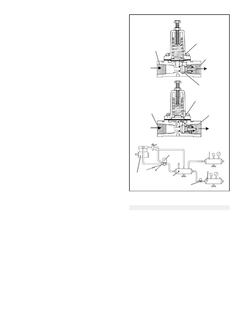
DIAPHRAGM
CHARGING
BELOW 100 PSI
SUPPLY
PORT
DELIVERY
PORT
SINGLE
CHECK
VALVE
CHARGING
ABOVE 100 PSI
SUPPLY
PORT
DIAPHRAGM
DELIVERY
PORT
SUPPLY
RESERVOIR
AD-SP
™
AIR
DRYER
COMPRESSOR
SC-PR
™
VALVE
REAR AXLE
RESERVOIR
FRONT AXLE RES.
FIGURE 6 - SC-PR
™
VALVE CHARGE POSITION*
Air Connection
Identification
System Connection
Supply .................... 1 SUP ....................... Connected to Supply (wet)
Reservoir
Delivery ................. 2 DEL ......................... Nipple Mounted to Front
Axle Service Reservoir
SC-PR
™
VALVE OPERATION
CHARGING
During initial air system build up, air flows from the supply
reservoir to the supply port of the SC-PR
™
valve. Air entering
the SC-PR
™
valve supply port is present beneath the
pressure protection diaphragm and simultaneously flows
through the single check valve portion into the front axle
service reservoir. With supply air pressure less than 100
psi, the pressure protection diaphragm, which functions as
a valve, remains seated on its inlet due to spring force above.
GOVERNOR
*Cutaway views are functionally correct, but do not represent current form of SC-PR
™
valve.