Bendix Commercial Vehicle Systems AD-SP SYSTEM PURGE AIR DRYER 10/04 User Manual
Page 13
13
FIGURE 9 - AD-SP
™
SYSTEM PURGE AIR DRYER
MOUNTING BRACKET DIMENSIONS
3. Do not locate the AD-SP
™
air dryer near heat producing
components such as the vehicle exhaust and make
certain adequate clearance from moving components
(e.g. drive shaft, suspension, pitman arm, etc.) is
provided.
4. Locate the AD-SP
™
air dryer on vehicle so that a minimum
of 1” clearance above the cartridge is available to allow
cartridge servicing. Additionally, provide access to the
bracket bolts so the unit may be removed when
necessary.
5. When choosing the mounting location for the AD-SP
™
air dryer, note the discharge line length requirements
stated under the heading Connecting the Air Lines,
elsewhere in this manual.
Important Note: Under normal operating conditions, the
maximum inlet air temperature for the AD-SP
™
air dryer
is 150 degrees Fahrenheit.
MOUNTING THE AD-SP
™
AIR DRYER
1. Install the AD-SP
™
air dryer by referring to Figure 2 and
drilling the triangular mounting hole pattern in a mounting
plate and then mounting the plate on the vehicle or by
drilling the mounting hole pattern in the area of the vehicle
chosen for mounting. Note: Check the vehicle manual
before drilling a frame member.
2. Important: The length of the three mounting bolts used
to attach the AD-SP
™
air dryer to the mounting plate is
very important. Refer to Figure 3. The threaded end of
the 1/2" - 13 UNC bolt must be between 1/8" below to
1/4" above the surface of the AD-SP
™
air dryer mounting
bracket surface when fully installed and tightened to
50 pound feet. Damage to the dryer body will result if
the bolt warning is ignored.
Measure the thickness of all materials that the three
mounting bolts must pass through. Small adjustments can
be made using flat washers under the bolt heads. Do not
use more than 3 flat washers.
3. Mount the AD-SP
™
air dryer on the vehicle using three
1/2" bolts (grade 5 min.) of the proper length and washers.
Torque to 50 lb. ft.
INSTALLING THE SC-PR
™
VALVE
1. Refer to steps 2A and 2B under Vehicle Preparation. If
the front axle (secondary) reservoir is:
A. A single reservoir and not part of a multiple
compartment, proceed to step 2.
B. One compartment in a multiple compartment,
proceed to step 3.
2. Locate the single check valve that protects and isolates
the front axle reservoir and remove it. Remove the air
line fitting from the single check valve and install the
same fitting in the SC-PR
™
valve. Install the SC-PR
™
valve and fitting in the reservoir port that was formerly
occupied by the single check valve. Reconnect the air
line to the SC-PR
™
valve. Refer to Figure 12.
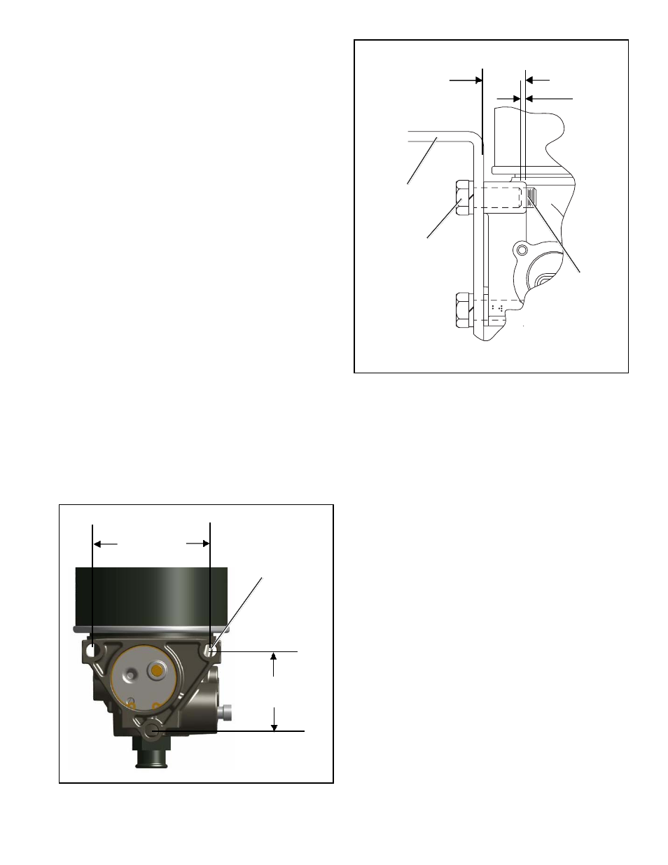
FIGURE 10 - AD-SP
™
SYSTEM PURGE AIR DRYER
MOUNTING BRACKET BOLT LENGTHS
2.835 INCHES
CENTER TO
CENTER
4.134 INCHES
CENTER TO CENTER
WIDTH (THICKNESS)
OF AD-SP
™
AIR DRYER
MOUNTING
BRACKET
MOUNTING
BOLT
1/8” BELOW
SURFACE
OF MTG.
BRACKET
VEHICLE FRAME
MEMBER
MOUNTING
BOLT
MOUNTING BOLT
1/4” ABOVE
SURFACE OF
MOUNTING
BRACKET
1/2” - 13 UNC
THREAD
(3 PLACES)