Bendix Commercial Vehicle Systems TU-FLO 750 COMPRESSOR 6/08 User Manual
Bendix, Tu-flo, 750 air compressor
1
®
SD-01-344
DESCRIPTION
The function of the air compressor is to provide and main-
tain air under pressure to operate devices in the air brake
and/or auxiliary air systems. The Tu-Flo
®
750 compressor
is a two cylinder single stage, reciprocating compressor
with a rated displacement of 16.5 cubic feet per minute
at 1,250 RPM.
The compressor assembly consists of two major
subassemblies, the cylinder head and the crankcase. The
cylinder head is an iron casting which houses the inlet,
discharge, and unloader valving. (See Figure 1.) The
cylinder head contains the air inlet port and is designed
with both top and side air discharge ports. Three water
coolant ports provide a choice of coolant line connections.
Governor mounting surfaces are provided at both the front
and the rear of the cylinder head. The head is mounted
on the crankcase and is secured by six cap screws. The
Tu-Flo
®
750 compressor is designed such that the cylinder
head can be installed in one of two positions which are 180
degrees apart. The crankcase houses the cylinder bores,
pistons, crankshaft and main bearings, and provides the
fl ange or base mounting surface.
Bendix
®
Tu-Flo
®
750 Air Compressor
BENDIX
®
TU-FLO
®
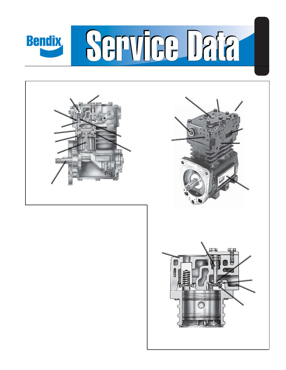
750 AIR COMPRESSOR
(CROSS SECTION)
BENDIX
®
TU-FLO
®
750 AIR COMPRESSOR
(EXTERIOR)
AIR DISCHARGE
WATER OUTLET
PIECE NO.
TAG
GOVERNOR
MOUNTING
PAD
CRANKCASE
PISTON RINGS
PISTON
CRANKSHAFT
CONNECTING
ROD
INLET VALVE
SEAT
UNLOADER
INLET VALVE
CYLINDER
HEAD
END VIEW OF CYLINDER HEAD
DISCHARGE
VALVE SPRING
DISCHARGE
VALVE
DISCHARGE
VALVE STOP
AIR INLET
CRANKCASE
INLET
INLET VALVE
SPRING
DISCHARGE
VALVE SEAT
UNLOADER
COVER
WATER
INLET
CYLINDER
HEAD