0 perforating, scoring & slitting – Baumfolder Flexifold: 1st Station (from 2005) User Manual
Page 38
PAGE 38
TP10494A
Slide the grooved perforator collar onto the lower
slitter shaft. The flat side of the perforator blade should just
touch the side of the groove in the perforator collar. (Item 6,
Figure 13.1-2)
Slide the perforator collar and blade holder to the de-
sired position on the slitter shaft. Re-install the pullout tire
assemblies on the right end of the upper and lower shafts.
Lock the slitter shafts in place by pushing in the knob
as you align the slitter shafts with the slitter shaft journal
assembly. Tighten the knurled knob. Then lock the blade
holder and perforator collar into position with the brass-
tipped set screw. (Item 4, Figure 13.1-2) Lock the pullout
tire assemblies in place by tightening the brass tipped set
screws. (Item 1, Figure 13.1-2)
The perforator stripper fits onto spreader bar above the
slitter shaft assembly and next to the perforating blade. (See
Figure 13.1-3) This strips the paper off for delivery and
prevents it from wrapping around the perforator blade.
13.0 PERFORATING, SCORING &
SLITTING
In addition to folding, your Flexifold Air Feed can
perforate, score and slit.
WARNING
Unplug power supply before working on equip-
ment. Be careful when handling perforator and slit-
ting blades. They are extremely sharp.
WARNING
Do not reach into the knife/slitter shaft area of the
machine while it is running
13.1 Perforating
The Flexifold can be used to perforate either the
folded sheet (to assist in making a right-angle fold) or to
perforate sheets delivered flat. BAUMFOLDER supplies
one standard 41-tooth perforator blade. Additional perfora-
tor blades are available from BAUMFOLDER.
On the operator side of the folder there is a knurled
knob beside the hand wheel. (See figure 13.1-1) This knob
holds the slitter shaft assembly in place. Loosen the knob
by turning counter-clockwise approximately 6 full turns.
Pull the knob toward you, leaving about 41.00mm gap
at the right end of the slitter shafts. This gap permits the
removal and installation of the slitter shaft accessories.
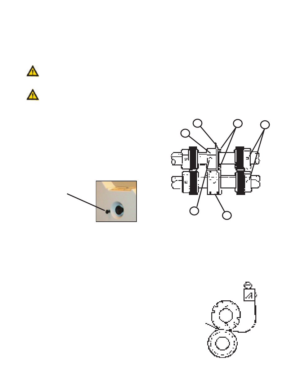
Loosen the setscrews (Item 1, Figure 13.1-2) in the
pullout tire assemblies on the right end of the upper and
lower shafts and remove the pullout tire assemblies.
The perforator blade, sharp surface down, should be
mounted loosely to the blade holder collar.(Item 2 & 3, Fig-
ure 13.1-2) Always be sure that the flat side of the blade is
against the blade holder. Loosen the brass-tipped set screws
(Item 4, Figure 13.1-2) in the blade holder before attempting
to place them on the slitter shafts.
The perforating blade holder assembly is then slid
onto the upper slitter shaft. Tighten the screws (Item 5,
Figure 13.1-2) holding the perforator blade to the blade
holder, aligning the blade to the holder. This allows for free
horizontal movement on the shaft.
Figure 13.1-1
Slitter Shaft Knob
Figure 13.1-2
1
2
3
4
5
6
Figure 13.1-3