Balboa Water Group EL8000 Configuration Guide User Manual
Instruments balboa, El8000 expansion options, Incorporated
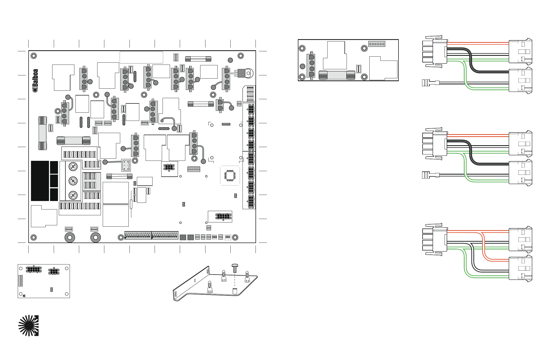
Output Features
Quadrant
J1 + W1
– 2-Speed Pump 1
3-B
J2 + W6 – Output tied to Pump 1 Low (J39 - P1-Lo)
4-B
– OR output tied to Circ Pump (J39 - Circ)
J3 + W7 – Circ Pump
5-B
J4 + W13 – Ozone (Separate Relay 120V or 240V)
7-B
J5 + W8
–
A.V.
6-B
J6 + W12 – 3-speed blower
8-B
J10 + W9
–
Spa Light (12V or 120V/240V) (Check J37 setting) 8-C
J7 + W2 – Misc (120V or 240V) (Check J47 setting)
2-C
J8 + W5 – Fiber Optic (12V or 120V/240V)
4-C
(Check J47 + J49 setting)
J9 + W4 – Option (on/off, no timeout) or
5-C
Mister (12V or 120V/240V) (Check J29 setting)
J11 + W14 – 2-Speed Pump 2
5-D
J12 + W10 – 2-Speed Pump 3 (W30 to J94)
7-D
W3
– Sets Transformer Voltage (120V or 240V)
4-E
(Setting must match transformer installed in system.)
EL8000 Mach 3 Configuration Guide
EL8000 Expansion Options
Instruments
Balboa
Incorporated
X-P632
Used for an additional 2-speed Pump output.
Relay control J2 plugs into the EXP I/O connector J36 on
the Main PCBA (Quadrant 7-E, near W10).
Expander boards that REPLACE the Blower function:
Relay control for these options is connected to J21 on the
Main PCBA (Quadrant 9-C, near W9). Do not use the
Blower Connector J6 if one of these is used.
X-P
PN 53544
Used for an on-off Device without a fuse.
X-B
PN 53310
Used for an on-off Device with 10A fuse.
X-P231
PN 53681
Used for an on-off Device with 30A fuse.
PN 53680
Document PN 40593_F
04-05-2007
PN 53914
X-Mount M
Used for mounting any Expander Board
in a metal enclosure.
Bracket attaches to heater mounting straps
Pump 5
P
ump 2
To
J
1
1
PS-25
Used to split the output from the Pump 2 Connector (J11)
into a single-speed Pump 2 and single-speed Pump 5.
White wire quick connect goes to Main PCB Red AC for
240 Pumps or to Wht AC for 120V Pumps.
PN 25094
White
Red
White
Green
Black
Green
White
Red
White
Green
Black
Green
Pump 4
P
ump 3
T
o
J12
PS-34
Used to split the output from the Pump 3 Connector (J12)
into a single-speed Pump 3 and single-speed Pump 4.
White wire quick connect goes to Main PCB Red AC for
240 Pumps or to Wht AC for 120V Pumps.
PN 25093
A
B
C
D
E
F
G
H
A
B
C
D
E
F
G
H
1
2
3
4
5
6
7
8
9
1
2
3
4
5
6
7
8
9
WHT AC (120V)
BLK AC
RED AC (240V)
J66
J65 J68
J64
J63 J67
J58
J57 J62
J54
J59
J60 J56
J61
J74
J75 J53
J95
J46
J55
J44
J52
J28
J27
J35 J43 J23 J32
TB1
FUSE 30A CLASS G
FUSE 30A CLASS G
F6
F7
K7
HTR2
HTR1
K6
K8
FUSE 1/2A 250V
F2
K4
K3
K2
J37
K16
J7
J8
K11
K9
K10
G
R
B
W
G
R
B
W
G
R
B
W
J9
J11
G
R
B
W
J1
G
R
B
W
G
R
B
W
J12
G
R
B
W
G
R
B
W
G
R
B
W
G
R
B
W
J2
J3
J4
J5
J6
J49
J47
BLK-A
BLK-A
P1-LO
CIRC
J39
K5
K13
K1
K14
W5
W4
W30
W14
W10
W6
W7
W8
W12
W9
W13
W15
W2
W1
W3
BARCODE
SWITCHBANK A
SWITCHBANK B
J17
J84
J15
J83
J22
K12
K15
J86
J92
J85
F1
J24
J82
TST
AUX. F
CFG
SEN. A
SEN. B
VAC
J91
J21
TV 1
J51
TV 2
J36
TRC6
J19
J18
UV
F5
FUSE 10A 250V
J90
J94
J76
J14
J93
J79
FUSE 3A 250V
F4
W
W
J10
U4
REMOTE
EXP I/O
ADCM
J69
J20
J25
J38
J81
J45
J41
J33
1
1
2
2
3
3
J29
1
1
2
2
3
3
12VAC-B
12V
AC-B
BLK-A
12VAC-B
1
2
3
J89
J26
J48
J50
J42
J77
MAIN P
ANELS
AUX P
ANELS
12 V
A
C
J16
J40
J34
J31
J73
J72
J71
J70
TORQUE
RANGE
FOR TB1:
27-30 IN. LBS.
HOT
BLACK
NEUTRAL
WHITE
HOT
RED
BALBOA INSTRUMENTS
, INC.
EL8000 Mach 3
COPYRIGHT 2005
P/N 22041 REV
A
MADE IN U
.S
.A.
G
R
B
W
J96
J101
J100
J13
J97
J30
Red
Black
White
Green
Sequencer
SS Pump
SS Pump
ELS-VALVE
Used to split the output from a single-speed Pump to allow
a Valve Sequencer to be powered by the pump’s output.
PN 22934
G
R
B
W
J1
W1
J2
J6
T30A 480V
X-P632
PN 53680
P/N 22909 REV B
ADCM SPLITTER KIT
Required when using a Menu-driven panel.
Kit includes PCB, stand-offs, and cable.
Note: Software v29 or higher required.
• J2 connects to ADCM IN (J69) on main PCBA.
• J3 connects to Menu Panel or Transceiver.
• J6 connects to tester or F.A.S.T. station.
PN 54530
J6
J3
J2
J1
TEST
Balboa
MADE IN U.S.A.
P/N 22039_ A
© 2006
ADCM SPLITTER
PN 54530