Balboa Water Group EL2000 Configuration Guide User Manual
Instruments balboa, Balboa, Incorporated
Output Features
Quadrant
J1
+ W1
– 2-Speed Pump 1
4-A
J2
+ W7
– Circ Pump or Fiber Optic (Separate Relay 120V or 240V) 6-C
J3
+ W2
– 1-Speed Blower (with 1-speed Pump 2) W15 to J97
7-C
– OR 1-Speed Pump 3 (with 1-speed Pump 2) W15 to J97
J4
+ W8
– Audio Visual (always hot - no relay)
2-A
J5
+ W12
– 2-Speed Pump 2 (with NO Blower on J3) W15 to J98
7-C
– OR 1-Speed Pump 2 (See J3/W2)
J9
+ W13
– Ozone (Separate Relay 120V or 240V)
6-C
J12 + W9
– Spa Light (12V or 120V) Check J37 Setting
5-B
EL2000 Mach 3 Configuration Guide
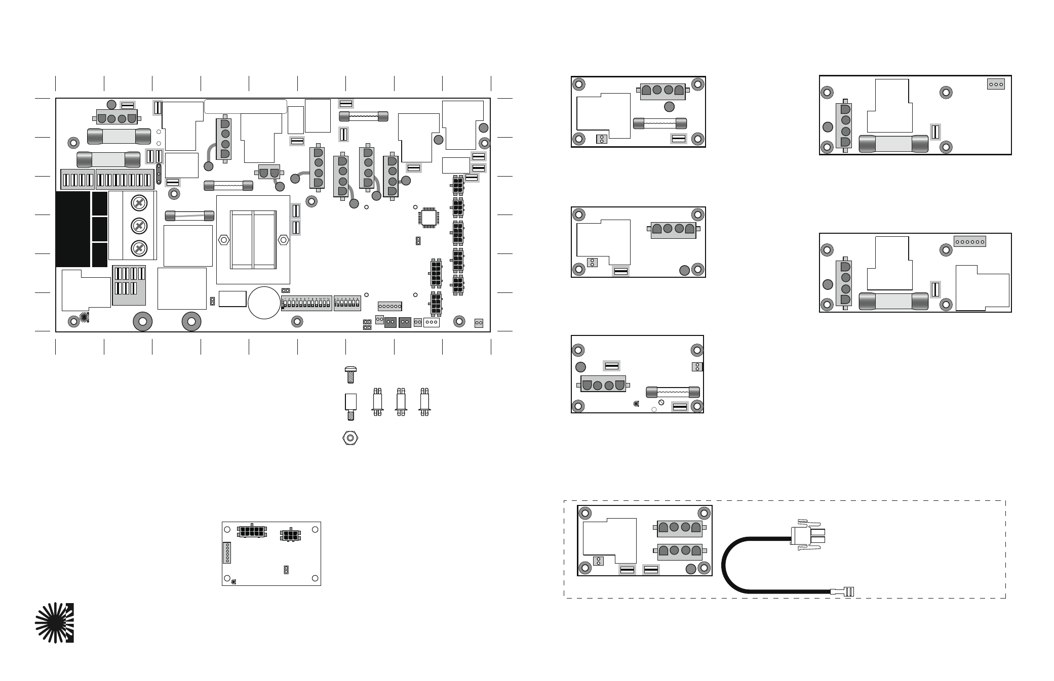
EL2000 Mach 3 Expander Board Options
Instruments
Balboa
Incorporated
G
R
B
W
J6
J3
J2
W12
K1
F10A 250V
F5
X-B
Used for a 1-speed Blower output ONLY.
• W15 (9-A) connected to J98 (8-B)
X-P
Used for a 1-speed Pump or Mister output.
• W15 (9-A) connected to J97 (9-B)
X-P632
Used for a 2-speed Pump output or for two 1-speed
Pumps. Can also be used for other optional setups.
• J6 on X-P632 connects directly to Black AC (1-C) on
the main EL2000 PCBA.
PN 53680
PN 53681
X-P231
Can replace the X-P in cases where branch circuit
protection is needed for high amperage devices that
would over-burden power input fuse F7 (1-B) on the
main PCBA. This allows J6 on the X-P231 to connect
directly to Black AC (1-C) on the main EL2000 PCBA.
X-O3
PN 53426
X-FOW Kit
Special setup with X-03 and Adapter PN 25338 to operate a fiber-optic light and
color wheel independently. Required to operate a Fiber Optic when a Circ Pump
is installed on Main PCBA at J2.
Document PN 40483_L
04-05-2007
PN 53912
G
R
B
W
G
R
B
W
J6
J7
J4
J5
J2
W12
K1
G
R
B
W
J6
J4
J2
W12
K1
Adapter PN 25338
To J5 on X-O3
To Spa Light on
EL2000
(120V Setup)
PN 53310
PN 53544
X-TB
Used for a multi-speed Blower (requires v29+ software and “bL” set to “2” or “3”)
Or can be used for a 1-speed Blower.
• W1 connects to Red or White AC on Main PCBA.
• J3 connects to Black AC on Main PCBA.
• J2 connects to J6 (Ext. Rly) on Main PCBA.
PN TBD
ADCM SPLITTER KIT
Required when using a Menu-driven panel.
Kit includes PCB, stand-offs, and cable.
Note: Software v29 or higher required.
• J2 connects to ADCM IN (J69) on main PCBA.
• J3 connects to Menu Panel or Transceiver.
• J6 connects to tester or F.A.S.T. station.
PN 54530
X-Mount P
Used for mounting any Expander Board
in a plastic enclosure.
Standoffs attach to heater mounting bracket.
PN 53933
A
B
C
D
E
F
A
B
C
D
E
F
1
2
3
4
5
6
7
8
9
1
2
3
4
5
6
7
8
9
RED AC
WHT AC
J53
J23
J19
J43
J48
K12
U4
J50
J52
BLK AC
J66
J65
J63
J64
J42
J54
J56
J55
J25
J57
J26
TB1
CLASS G
FUSE 30A
CLASS G
FUSE 30A
F6
F7
F4
K4
W1
F2
K7
T1
HTR2
HTR1
FUSE
0.3A 250V
K6
K8
G
R
B
W
J79
J46
J45
J81
12VAC
ADCM
J37
J4
J7
J74
W8
1
2
3
FUSE
3A 250V
TORQUE
RANGE
FOR TB1:
27-30 IN. LBS.
HOT
BLACK
NEUTRAL
WHITE
HOT
RED
Balboa
J11
J8
BARCODE
G
R
B
W
W
W
J12
J14
W13
W12
K13
W20
W15
BALBOA INSTRUMENTS, INC. MADE IN U.S.A.
EL2000 TC MACH III COPYRIGHT 2005
P/N 22896 REV B
K10
J2
MAIN
PANEL
MAIN
PANEL
MAIN
PANEL
AUX
PANEL
AUX
PANEL
J9
J5
J6
K3
J3
K2
W2
F5
W9
W7
REMOTE
K11
K9
J1
K1
G
R
B
W
G
R
B
W
G
R
B
W
J86
J80
J60
J69
J20
J10
FUSE 10A 250V
J39
J71
J70
J98
J89
J91
J17
J15
J13
J83
J22
J24
J82
J36
TST
SENS. A
SENS. B VAC
EXT. 2SP PUMP 3
EXT. RLY
AUX. F
J72
CFG
SWITCHBANK A
SWITCHBANK B
J90
J97
G
R
B
W
J85
G
R
B
W
J1
W1
J7
J6
F30A 480V
X-P231
PN 53681
P/N 22909 REV B
G
R
B
W
J1
W1
J2
J6
F30A 480V
X-P632
PN 53680
P/N 22909 REV B
J6
J3
J2
J1
TEST
Balboa
MADE IN U.S.A.
P/N 22039_ A
© 2006
ADCM SPLITTER
PN 54530
G
R
B
W
J1
J3
J5
J2
W1
RED/WHT
BLK/12VAC-A
PN 22051_X1
2006
BLOWER
F1
Pb
Balboa
C