Installation – B&D Mfg Smart User Manual
Page 7
7
ALL THE PUMP YOU NEED AND MORE
Revised 7-5-12
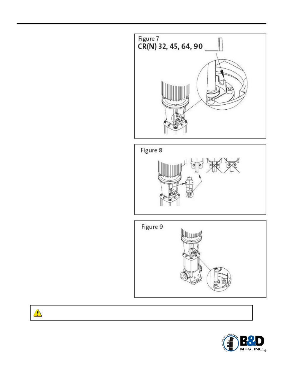
CR 32 & 45 –
1. Place the plastic adjustment fork under
the cartridge seal collar (see Figure 7).
2. Fit the coupling on the shaft so that the
top of the pump shaft is flush with the
bottom of the clearance chamber in the
coupling (see Figure 8).
3. Lubricate the coupling screws with an
anti-seize and lubricating compound.
Tighten the coupling screws (finger tight)
while keeping the coupling separation
equal on both sides and the motor shaft
keyway centered in the coupling as shown
in Figure 6a (page 6).
4. When the screws are tight enough to keep
the couplings in place, then torque the
screws evenly in a crisscross pattern.
Torque coupling screws to 62 ft.-lbs.
5. Remove the adjustment fork from under
the cartridge seal collar and replace it to
the storage location (see Figure 9).
6. Check to see that the gaps between the
coupling halves are equal. Loosen and
readjust if necessary.
7. Be certain that the pump shaft can be
rotated by hand. If the shaft cannot be
rotated, or it binds, disassemble and
check for misalignment.
Installation
WARNING: CFC_ Multizones are a non-pressurized unit and should NEVER be pressurized
for any reason.