Drive display/operation – B&D Mfg Smart User Manual
Page 10
10
ALL THE PUMP YOU NEED AND MORE
Revised 7-5-12
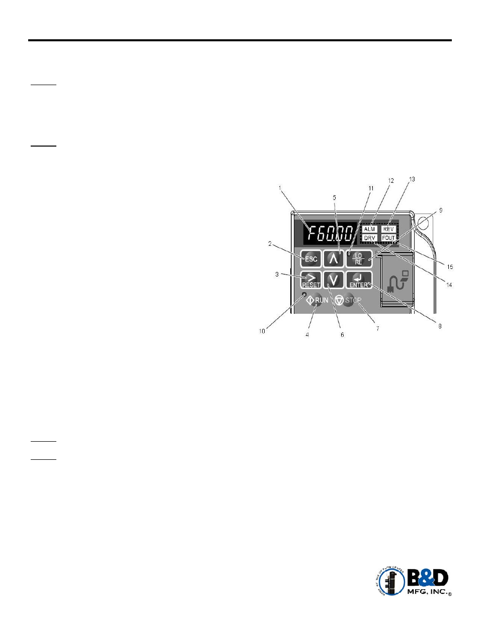
Drive Display/Operation
Navigating and Changing Drive Parameters –
The start screen on the LED will be a frequency reference. This will show the operating frequency of the drive.
NOTE: Drive must be on this screen to start operation.
Pressing the up arrow
on the display face will allow navigation for multiple levels of information on the
drive.
Displays “For” on the LED. This indicates the drive will turn the motor in a forward direction only.
NOTE: If the drive is NOT ABLE to produce pressure greater than 20 psi, the motor could be wired
incorrectly. Check motor rotation to verify. Rotate any two of the three motor leads for terminals U,
V & W on the drive to correct rotation.
Displays the output frequency of the drive to the motor.
Displays the output amps to the motor.
Displays the output voltage to the motor.
Displays “Mon” for Monitoring Menu. This menu displays
system operations, such as:
Real-time output power of drive (kW): U1-08
Current fault : U3-01
Previous fault: U3-02
Accumulated operation time (hrs): U4-01
Total power consumption (kW): U4-10
Sensor feedback level: U5-01
Displays “STUP”, referring to the Set Up Menu. This allows navigation of the four parameters that can be
adjusted. (Instruction to follow on a later page.)
B5-19 System Pressure Setting
Default = 0 psi (Must be set for pump to operate.)
B5-15 Sleep Frequency
Default = 25 Hz (disabled)
B5-12 Dry Run Protection
Default = 0 (disabled)
B1-02 Key Pad Enabled
Default = 0 (enabled)
NOTE: Pressing the ESC (escape) button allows the drive menu to go back one step.
NOTE: The drive will not allow operation unless the start screen is displayed (frequency reference).
This screen can be displayed by pressing the ESC key several times.