Section 5: assembly procedures, Mounting a tfm17 on an autocue “magic arm, Attach “magic arm” to the mounting plate – Autocue TFM17 User Manual
Page 10: Assembly procedures, Tfm17 assembly and installation guide
TFM17 Assembly and Installation Guide
www.qtv.com
7
www.autocue.com
Issue
#
: 081
017
©
2003
-200
8
Au
to
cu
e Grou
p Ltd
S
ECTION
5:
Assembly Procedures
An Autocue Talent Feedback Monitor (TFM) can be used with almost any industry-
standard camera and tripod combination. The TFM17 is usually used in conjunction
with Autocue’s larger On-Camera Units.
Assembling and mounting your TFM17 involves:
•
attaching the mounting arm to the OCU mounting plate
•
attaching the monitor to the mounting arm
•
connecting required cables
•
ensuring all connections and fixings are secure.
The TFM17 is supplied with the mounting plate already attached to the back of the
monitor using standard VESA fittings.
N
OTE
:
A feedback monitor is usually ordered at the same time as
OCU with the mounting plate already attached to the OCU
mounting bracket. If TFM17 is ordered separately refer to
section 5.2 for instructions on attaching the mounting plate to
the OCU bracket.
5.1: Mounting a TFM17 on an Autocue
“Magic Arm”
Talent feedback monitors should be attached to Autocue’s standard OCU mounting
bracket using the recommended “Magic Arm” bracket.
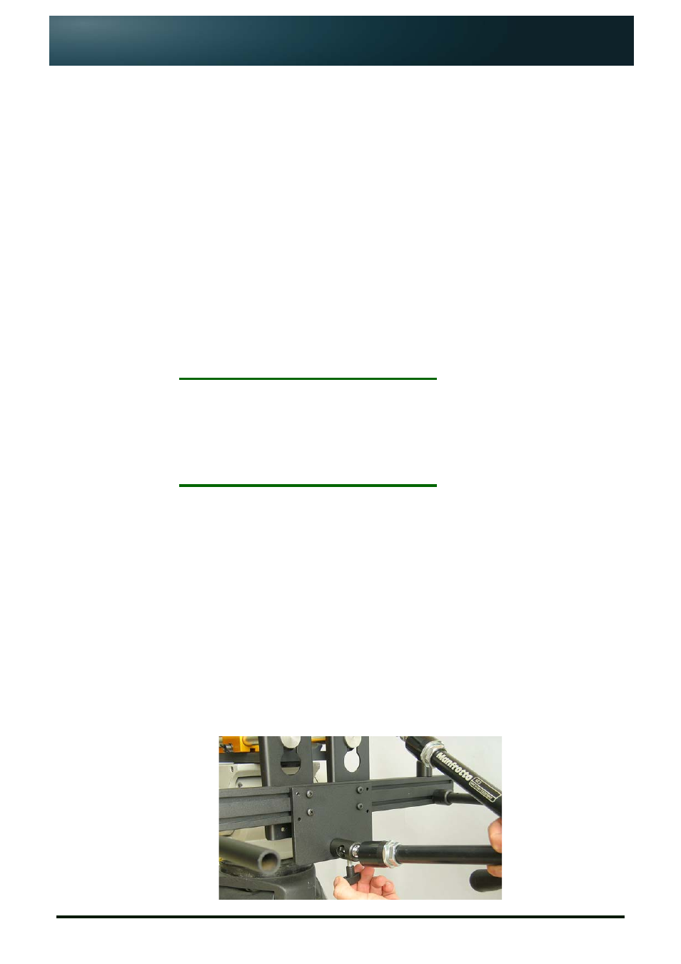
5.1.1: Attach “Magic Arm” to the mounting plate.
1. Insert one end of the “Magic Arm” bracket into the mounting plate
attached to the OCU mounting bracket.
2. Securely fasten the locking screw.