On-camera unit quick assembly instructions, Installing usb-serial converter, Further information – Autocue On-Camera Unit User Manual
Page 4: Attach prompter display, Adjust weight and balance, Connect cables
On-Camera Unit Quick Assembly Instructions
www.qtv.com
4
www.autocue.com
Issue
#
: 080
612
©
2003
-200
8
Au
to
cu
e Grou
p Ltd
2. Move the hood down the vertical bars to position the unit
so that the lens of your camera will be centred in the
glass plate of the hood.
3. Secure in the required position by tightening the locking
clamps on the rear of the hood.
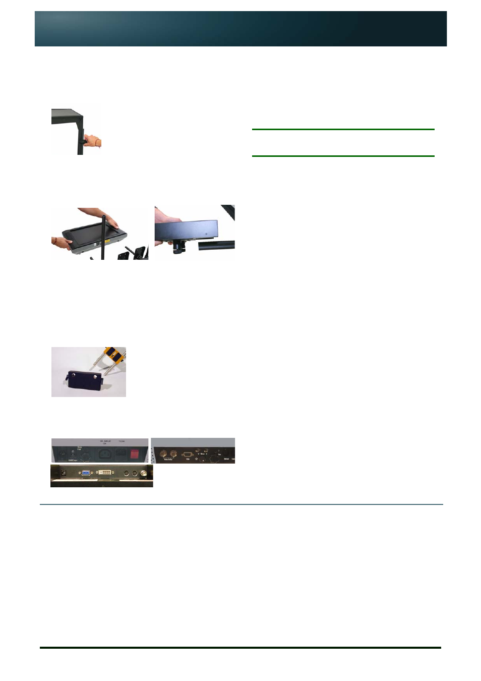
Attach prompter display
1. Slide the horizontal rods of the Bracket Set into the
mounting holes in the prompter display chassis or the
tube clamps on the base of the unit.
2. Secure in the required position by tightening the locking
clamp on the side of the chassis or the tube clamp.
3. Repeat for the other clamp.
Adjust weight and balance
Adjust the position of the camera and the OCU on the
tripod so that the whole assembly is stable and that the
lens is positioned in the centre of the glass.
If required, counter-balance weights can be fitted.
Connect cables
Plug the required video input and power cables into the
appropriate sockets on the display unit.
5.
Installing USB-Serial Converter
If you have purchased a USB To Serial Converter
supplied by Autocue, follow the steps outliend below to
install it.
The converter allows you to connect a serial scroll
controller to your computer using a standard USB port.
N
OTE
:
Do NOT attach the USB-Serial Converter to your
computer before installing the drivers.
1. Place the mini-CD supplied with the converter into the
CD/DVD drive of your computer.
A web browser window will be displayed.
2. In the USB Version 1.1 section of the browser window,
locate the entry for the USB To Serial Cable (DB-9M)
FTDI Chip and click on Installation Driver.
3. Double-click the Win 98-XP Driver.exe and follow the on-
screen instructions.
4. When the drivers have been successfully installed,
remove the CD.
5. Plug the converter into a USB port on your computer and
use the Device Manager to see that the device has been
correctly identified as a serial port.
6. Note the number of the COM port that has been assigned
to the converter. This will be required when configuring
any scroll controller that is attached to the converter.
Further information
•
If you require more detailed instructions please refer to the CD included in your shipment.
•
Further help and guidance may be obtained from our web sites (URLs at the bottom of the
page) or contact Technical Support via email: [email protected] or [email protected].