AJA FR2 User Manual
Page 5
1
5
AJA FR1 and FR2 Video Card Frames User Manual
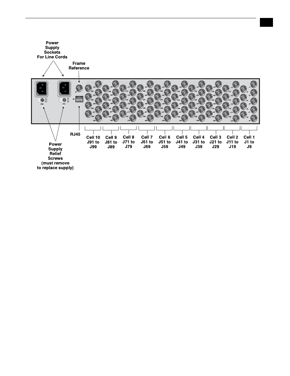
FR2 Multiple Card Frame, Rear Panel Connectors
Input/Output BNCs (groups of 9 per cell)
—
Each unique slot in the FR1/FR2
frames connect to a group of 9 BNCs on the frame rear panel. The actual
function of the BNC connectors is dependent on the video card installed.
Each group of 9 BNCs corresponds to the card installed in the same position;
for example the right-most card connects to the right-most group of
connectors at the position on the rear panel.
Frame Reference BNC
—
Both the FR1 and FR2 frames have this frame reference
input BNC connector, which feeds an external reference video signal to all
modules installed in the frame. How the signal is distributed differs for the
FR1 and FR2 frames. Additionally, individual modules can usually be strapped
as to whether external reference is distributed from the frame or directly to
BNCs on the module’s corresponding cell group (the 9 BNCs on the rear
panel). See the “Note” below for more information on looping reference
inputs in the cell group.
FR1 Frame: the external reference signal is distributed passively to all frame
modules. Cards installed in the frame should have “FRAME” reference
selected, and one and only one card in the frame should have
“TERMINATION” set to “ON.” All other cards in the frame should have
TERMINATION set to “OFF.”
FR2 Frame: the external reference signal is distributed by an in-frame
distribution amplifier to all frame modules. This system terminates the Frame
Reference input BNC and buffers the signal to all slots. Cards installed in the
FR2 frame should
have “FRAME” set for reference select, and all cards should
have TERMINATION set to “OFF.”