User controls and indicators – AJA RD5CE User Manual
Page 5
1
5
AJA RD5CE Dual Universal D/A Converter User Manual
User Controls and Indicators
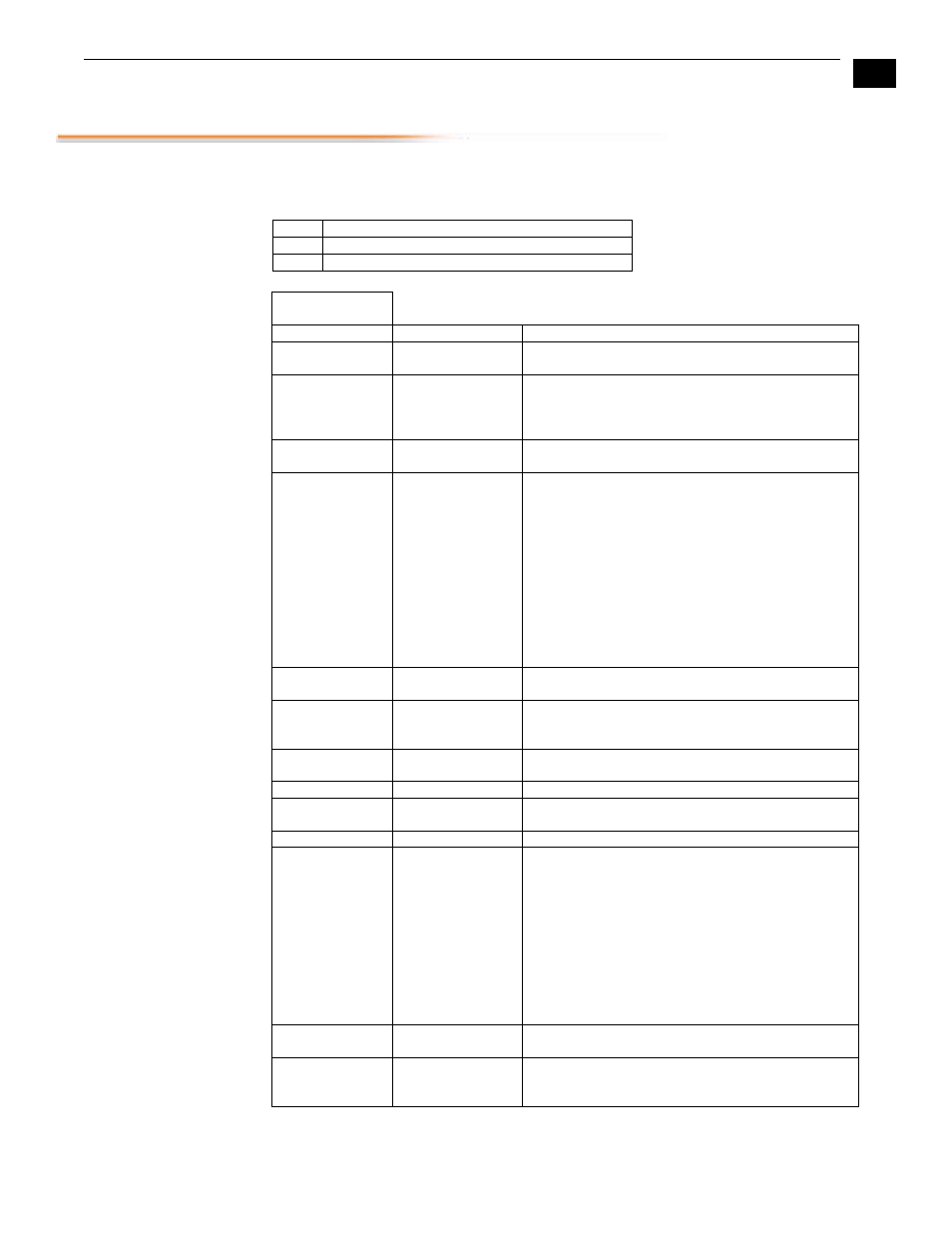
The user interface for the RD5CE includes two dipswitches, a six position for control of
Channel 1 and a four position for control of Channel 2 and 2 LEDs.
LED FUNCTION
1
Video present on Channel 1
2
Video present on Channel 2
Channel 1 DIP
Switches
FUNCTION DESCRIPTION
DETAILS
1
Output Selection
UP = Component
DOWN = Composite
2
Output Selection
UP = YUV/YC if SW1=up Output = YUV, if
SW1=down Output = YC + 1 composite
DOWN = RGB is SW1=up, if SW1=down
Outputs all composite
3
Output Selection
UP = BETACAM 525 levels
DOWN = SMPTE/EBU-N10 Levels
4
Blanking
UP = Narrow: Vertical
(line numbers indicate where video starts)
line 13, field 1; line 12, field 2 (525 line)
line 10, field 1; line 322, field 2 (625 line)
Horizontal (active video line duration’s)
ITU-R.470 (720 pixels PAL/NTSC)
DOWN = Wide:
line 20, field 1; line 20, field 2 (525 line)
line 23, field 1; line 336, field 2 (625 line)
Horizontal (active video line duration)
ITU-R/SMPTE (710 pixels NTSC, 702 pixels PAL)
5
Pedestal
UP = Add Pedestal
DOWN = No Pedestal
6
Test
UP = Normal
DOWN = Color Bar Test Pattern
(Requires valid SDI input)
Channel 2 DIP
Switches
FUNCTION DESCRIPTION
DETAILS
1
Output Selection
UP = Component
DOWN = Composite
2
Blanking
UP = Narrow: Vertical
(line numbers indicate where video starts)
line 13, field 1; line 12, field 2 (525 line)
line 10, field 1; line 322, field 2 (625 line)
Horizontal (active video line duration’s)
ITU-R.470 (720 pixels PAL/NTSC)
DOWN = Wide:
line 20, field 1; line 20, field 2 (525 line)
line 23, field 1; line 336, field 2 (625 line)
Horizontal (active video line duration)
ITU-R/SMPTE (710 pixels NTSC, 702 pixels PAL)
3
Pedestal
UP = Add Pedestal
DOWN = No Pedestal
4 Test
UP
=
Normal
DOWN = Color Bar Test Pattern
(Requires valid SDI input)