Block diagram i/o connections – AJA RD5CE User Manual
Page 4
4
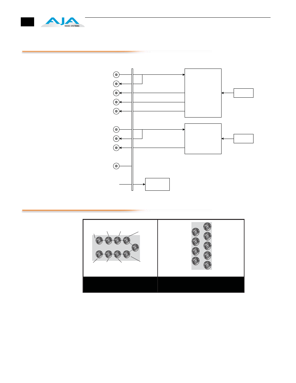
Block Diagram
I/O Connections
FR1 and FR2 BNC Connector Assignments, RD5CE Card Module
When the RD5CE module is installed in an AJA FR1 or FR2 frame, a corresponding
group of 9 BNCs on the rear panel then provide I/O for the module. The
illustration above shows the connector assignments for both the FR1 and FR2
when used with the RD5CE.
Power Regulation
+6.5V Power
From Rackframe
Redundant Supplies
Rackframe
Backplane
SD SDI Video 1
Configuration
Switches
Digital to Analog Converter
And Composite Encoder
Configuration
Switches
No Connect
Component/Composite Analog
Video 1
SD SDI Video 2
Composite Analog Video 2
Digital to Analog Converter
And Composite Encoder
J1
J3
J5
J7
J9
J2
J4
J6
J8
J1
J2
J3
J4
J5
J6
J7
J8
J9
FR1 Frame Layout
RD5CE Rear Panel
FR2 Frame Layout
RD5CE Rear Panel
UNUSED
REF In
SDI In 2
SDI In 2
SDI Out 2
SDI Out 2
Comp Out 2
Comp Out 2
Comp/Y/B/Pb 1
Comp/Y/
B/Pb 1
SDI In 1
SDI In 1
SDI Out 1
SDI Out 1
Comp/-/G/Y 1
Comp/
-/G/Y 1
Comp/C/R/Pr 1
Comp/C/
R/Pr 1