Simplified block diagram, Gen10 connections, User controls – AJA GEN10 User Manual
Page 5
GEN10 Mini-Converter v1.0r2
www.aja.com
5
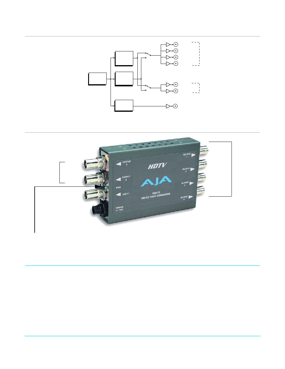
Simplified Block Diagram
GEN10 Connections
User Controls
The user interface for the GEN10 is an 8-switch DIP accessible through a cut-out in the
bottom of the unit, and an internal jumper block accessed by removing the GEN10 cover
(secured by 4 screws).
Use the jumper to configure the NTSC Pedestal. Then use the DIP switches to configure
the sync generator formats.
Factory default settings are internal jumper installed (NTSC with Setup: 54 mV pedestal
offset), and all the DIP switches in the leftmost position. The exact function of the jumper
settings and each DIP switch are described in
Master
Timebase
Selectable as a group for
HD: Trilevel
720 or 1080
(multiple formats: see specifications)
or
SD: 75% Color Bars or Blackburst
PAL or NTSC
AES
Generator
SD
Sync
Generator
HD
Sync
Generator
SD
HD
SD
HD
SW1
SW2
AES 11 Output
Group 1
Group 2
Output 1
Output 2
Output 3
Output 4
Output 5
Output 6
Selectable as a group for
HD: Trilevel
720 or 1080
(multiple formats: see specifications)
or
SD: 75% Color Bars or Blackburst
PAL or NTSC
Configuration is
Determined by
DIP switch on
other side of
Converter
2nd
Power LED: When Green, this LED indicates
the GEN10 is powered up.
Output Group
Output 5
Output 6
AES 11
Output
Output 1
Output 2
Output 3
Output 4
1st
Output Group
Either Output Group can be set to SD or HD
+ 5 VDC
Power
Input