Wiring, Bulb replacement – Wolo 7000 SERIES Infinity 1 User Manual
Page 4
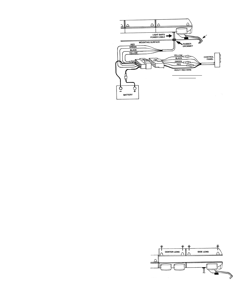
WIRING
21. WARNING: Failure to wire the light bar
correctly could result in permanent damage
to the light bar, the vehicle's electrical
system and/or cause a fire. If any switch,
fuse or wire is replaced, they must meet or
exceed specifications rating specified in this
manual. Any deviation to the electrical
specifications is at the installers/users risk.
IMPORTANT: Disconnect the vehicles
battery before beginning any wiring.
IMPORTANT: The heavy gauge RED wire
must be connected to an appropriate inline
fuse (included with light bar) at the point of
the battery connection. The fuse should
never be more then ten-(10) inches from the
battery post. See fig. 8.
22. Route the heavy gauge RED & BLACK wires to the vehicles battery. If the power wires pass
through any drilled holes or firewall, always use a rubber grommet to protect the vehicle.
23. Connect the light bar's BLACK wire to the (-) negative battery post. Make sure the connection is at
a clean location free from corrosion or oxidation.
24. Secure the light bar's RED wire to the (+) positive battery post using the fuse holder provided with
the 25-amp fuse. Make sure the connection is at a clean location free from corrosion or oxidation.
25. Make sure all wire connections are properly insulated so to prevent shorts.
26. Make sure all wires are securely fastened to vehicle using plastic wire ties or electrical tape (not
provided). WARNING: Carefully inspect the interior driver's area to make sure the light bar wires or
the vehicle's electrical system wires are not interfering with the operation of vehicle's controls;
accelerator, brake, clutch pedals and etc.
26. Reconnect the vehicle’s battery. Installation is complete.
BULB REPLACEMENT
WARNING: A serious injury can result if the bulb is touched when hot. Always allow five (5) minutes for
the bulb to cool before removing. Always wear gloves and eye protection when removing the bulb
because Halogen bulbs are pressurized and if broken, glass can be projected.
BULB REPLACEMENT FOR TOP (LEFT & RIGHT SIDE ROTATING LIGHTS)
27. You will need to remove the lens from the light bar to change the
bulb. Remove the four screws that secure the lens. Once the
four screws are removed, the lens can be removed from the
light's base. See fig.9.
28. Replacement bulb type: use only halogen 796/ 35watt halogen,
12 volt. Current draw: 2.73 amps.
29. Rotate the reflector by turning it with your finger until the bulb
can be easily be accessed for removal.
Fig. 8
STRAP
WINDOW LEDGE
POWER PLUG
REPLACEMENT FUSE SIZE FOR
CONTROL PANEL
YELLOW WIRE 7.5 AMP
GREEN WIRE 10 AMP
RED WIRE 15 AMP
HEA
VY
BLACK WIRE
HEAVY RED WIRE
25 AMP FUSE
PROVIDED
Fig. 9