Mounting & wiring switch control panel – Wolo 7000 SERIES Infinity 1 User Manual
Page 3
12. The hook of the stainless steel strap that is secured to the vehicle's window ledge has a hole located
in the middle. Use the hole as a template and drill a 5/32’’ hole and install the self-tapping screw
provided. IMPORTANT: The installer may have to lower headliner and inspect the selected location to
ensure that there are no components, wires and or any other vehicle part that could be damaged by
drilling. See Fig. 4.
13. Place the weather-strip back into position.
14. Insert the power cable into the roof’s access hole that was
drilled earlier using the rubber grommet. Route the power
cable into the B-pillar.
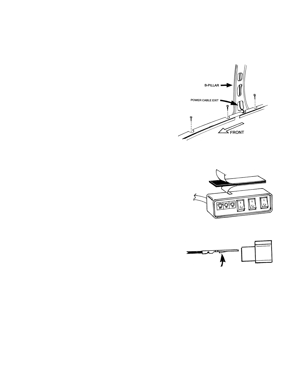
15. The power cable will make an approximate 90° bend into the
B-pillar. Depending on the vehicle, this can sometimes be
difficult, but it is the recommended procedure for proper
installation. Installation will vary for each make and model
vehicle and it is up to the installation technician's discretion
whether to route the power cable as recommend through the
B-pillar or use an alternative routing method. Route the power
cable down to the bottom of the B-pillar and the pull the full
length of the cable into the interior of the vehicle. See Fig. 5.
16. Make sure the power cable has been completely pulled into the vehicle, use silicon or similar
waterproof material around the grommet and power cable to ensure a waterproof installation.
MOUNTING & WIRING SWITCH CONTROL PANEL
17. The light bar's switch control panel needs to be mounted in a location
that can easily be reached. Make sure the mounting surface is clean
and free of dust, dirt, oil, wax and etc. Using the double face tape
provided, secure the control panel to the selected mounting location.
See fig. 6.
18. Route the light bar's power cable to the switch control panel that was
mounted in the dash area in step #17.
19. The power cable has four-(4) different colored wires that need to be
inserted into the plastic power plug. The plug is labeled showing the
correct position for each color wire. IMPORTANT: Each of the four-
(4) colored wires has a flat terminal with a protruding tab in the middle
of the terminal. The tab locks the terminal into the plastic power plug.
When inserting the terminal into the plug, the tab should be facing as
shown in fig# 7. NOTE: The plug's middle position between the
heavy gauge red and black wire is not used for this model light and
should remain empty.
20. Connect the switch control panel's female plug to the power cable's male plug as shown in figure 8.
IMPORTANT: There are three inline fuses connected to the switch control panel wires:
Red wire: Controls upper rotating lights, replace with 3AG 15 amp fuse
Green wire: Controls alley and takedown lights, replace with 3AG 8 amp fuse
Yellow wire: Controls flashing marker lights, replace with 3AG 8 amp fuse
Fig. 5
Fig. 6
Double Faced Tape
Power Plug
PUSH CONNECTORS INTO MATCHING
COLOR SLOTS ON FEMALE PLUG
Fig. 7
LOCKING TAB
SIDE VIEW OF
FEMALE PLUG