I/o wiring, Wi-i/o 9-u2, Digital output – Weidmuller WI-I/O 9-U2: Wireless Mesh I/O & Gateway Installation Guide V1.5 User Manual
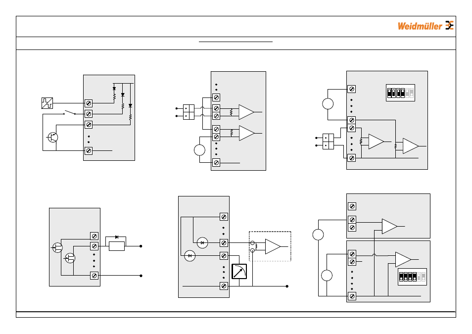
Page 2: Digital input, Differential current inputs (ai1&2), Single ended current input (ai3&4), Analog output single ended voltage input
FCC Statutory Requirement
Unlicensed operation limits the radio power. High gain aerials may only be used to compensate for cable losses.
_
+
Max 30VDC
0.2A
V-
DIO1
DIO2
Digital Output
Voltage Free Contact
Transistor
Switch Device
V+
V-
DIO1
DIO2
GND
WI-I/O 9-U2
Digital Input
DC
Load
WARNING - EXPLOSION HAZARD - DO NOT DISCONNECT CIRCUITS WHILE LIVE, UNLESS AREA IS KNOWN TO BE NON-HAZARDOUS
V-
AIN2+
AIN2-
ALS +24V
Externally
powered sensor
AIN1+
AIN1-
Loop
powered
sensor
Power
supply
Differential Current Inputs (AI1&2)
+
_
+
-
mA
0-25V
Sensor
+
-
V
V-
AIN3
AIN4
ALS +24V
Single Ended Current Input (AI3&4)
ALS +24V
Loop
Powered
Sensor
+
-
mA
Externally
powered
sensor
Power
supply
+
_
0-5VDC
Sensor
+
-
V
V-
AIN3
AIN4
1
ON
2
3
4
5
6
Dip Switch setting
for Current I/P
Dip Switch setting
for Voltage I/P
V-
AOT1
AOT2
ALS +24V
PLC
AI
COM
+
-
AIN1+
AIN1-
Differential Voltage
Inputs (AI1&2)
Single Ended Voltage Input
(AI3&4)
Analog Output
Single Ended Voltage Input
WI-I/O 9-U2
WI-I/O 9-U2
WI-I/O 9-U2
WI-I/O 9-U2
WI-I/O 9-U2
GND
GND
GND
GND
GND
DIO3
TTL CMOS
Output
inst_WI-IO 9-U2_1.5.vsd
WI-I/O 9-U2
1
ON
2
3
4
5
6