Weidmuller WI I/O 9-1: Wireless I/O Transceiver 4DI/2DO/2AI/2AO/1PI v1.9 User Manual
Wi-i/o 9-1, Installation guide, Aerial installation
Weidmuller Rev. 1.9
FCC Notice
This device complies with Part 15.247 of the FCC Rules.
Operation is subject to the following two conditions:
1) This device may not cause harmful interference and
2) This device must accept any interference received, including interference
that may cause undesired operation
THIS EQUIPMENT IS SUITABLE FOR USE IN CLASS 1 DIVISION 2
GROUPS ABC AND D OR NON HAZARDOUS LOCATIONS ONLY
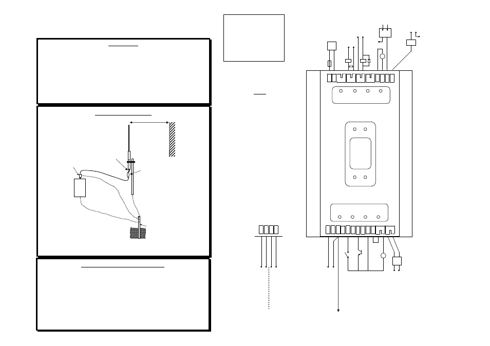
Aerial Installation
WI-I/O 9-1 I/O Installation
Power supply: (A) 12-24VAC 1.5 Amp CSA certified Class 2
(B) 15-30VDC 1.5 Amp CSA certified Class 2
(C) Supply battery or 11-15VDC
(D) Solar panel with solar battery
Choose option and wire as shown
WI-I/O 9-1
Installation Guide
1m minimum
COLINEAR
ANTENNA
MAST
EARTH STAKE
IF GROUND CONDITION IS POOR
INSTALL MORE THAN 1 STAKE
INSTALL AERIAL ABOVE
LOCAL OBSTRUCTIONS
ANT
WI-I/O
SURGE
ARRESTOR
(OPTIONAL)
COAXIAL CABLE
WEATHERPROOF
CONNECTORS WITH
“3M 23” TAPE
STRESS RELIEF LOOP
PROVIDE GOOD
GROUND
CONNECTION TO
MAST, MODULE
AND SURGE
ARRESTOR
GND
ANTENNA INSTALLATION
Antennas should be installed by experienced Contractors.
11-15VDC Supply or
Optional 12V Backup
Battery
to 12 Amphour for AC/DC
to 100 Amphour for Solar
- +
DC Relay
Supply
AC Relay
Supply
Analog Outputs -
See Note 2.
+
To +24V
loop supply
-
+A
I 2
-
+A
I 1
+2
4V
D
I
3
S
O
L
D
I
2
D
I
1
G
N
D
C
O
M
D
I
4
S
U
P
2
S
U
P
1
B
A
T+
D
O
1
D
O
2
D
O
4
D
O
3
G
N
D
+
24
V
A
O
1
A
O
2
P
O
1
2
3
4
OUTPUTS
1
2
3
4
INPUTS
WI-I/O 9-1
RADIO TELEMETRY MODULE
2A
+ -
-
+
To Com
-
-
-
+
+ -
+
Ext. Powered
AnalogTransducer
Loop
Powered
Analog
Transducer
Digital Input
Voltage Free
Contact
OR
Transistor
Device
To Earth
Connection
DC Supply
15-30VDC
min 17VDC
for Battery
Charging
S
O
L
G
N
D
S
U
P
2
S
U
P
1
AC Supply
12-24VAC
min 15VAC
for Battery
Charging.
Do not earth
SUP1 or
SUP2
connections
12V Solar
Panel Supply
max 20VDC
max 30W
panel
Output Counter Ext. DC
Supply 30VDC, 500mA max
Digital Outputs -
See Note 1.
NOTES
Digital Outputs are Relay
contacts.
For ratings refer to User
Manual.
AC Load use 10nF 250V
Surge Capacitor.
DC Load, use Bypass
Diode.
Analog Outputs are either
Loop Powered or Externally
Powered - Output Loops are
sink to earth (not floating).
All I/O must be SELV
CAUTION!
For continued protection
against risk of fire, replace the
module fuse only with the
same type and rating
WARNING!
EXPLOSION HAZARD
DO NOT DISCONNECT
WHILE CIRCUIT IS LIVE
UNLESS AREA IS KNOWN
TO BE NON -HAZARDOUS
–
+