Weidmuller PU-Overvoltage in Mains Control User Manual
Page 4
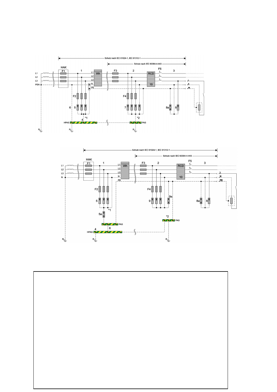
Protection according to IEC
61024-1, IEC 61312-1
Protection according to IEC
60364-4-443
Fig. 1 Overvoltage protective equipment in TN network
Fig. 2 Overvoltage protective equipment in TT Network with the 3+1 PU Module
1
Main supply system
2 Electrical
circuit
distributor
3
Branch circuit area
4
Main equipotential bonding strip
5
Overvoltage protection protective equipment Class I for lightning protection potential equalizer
5a
3+1 PU Unit with N-PE Lightning current arrestor
6
Main equipotential bonding conductor
7
Overvoltage protection-protective equipment Class II PU 3 C / PU 4 C
8
Overvoltage protection-protective equipment Class III PU D in the TN System
8a
Overvoltage protection-protective equipment Class III PU D in the TT System
9
9a Overvoltage protection protective equipment Class II PU 3+1 C for TT System
10
RCD ( Residual-current device)
11 Arrester
disconnector
HAK Service
panel
R Earth
R
e
Equipment earth
Wh
Measuring device
F1
Input terminal fuse
F2
Fuse for PUxB necessary only by max. 160 A (depending on type of routing ), if F1> 160 A.
F3
Fuses for Electrical circuit distributor
F4
Fuse for PUxC necessary only by max. 125 A (depending on type of routing), if F1> 125 A.
F5
Circuit breaker 16 A
*1)
Construction before taking measurements should be agreed with the local ESC.
*2)
If a lightning protecting equipotential equalizer exists, then it must be connected to the earthable points
of the overvoltage protective equipment.