Weidmuller G478 Ultra SlimPak User Manual
Page 2
Description
Application
‘Touch-Sample’
Technology
Status LEDs
The Ultra SlimPak Model G478 is a DIN rail mount, frequency input signal conditioner with 1800Vdc
isolation between input, output and power. The field configurable input and output offer flexible, wide ranging
capability for variable frequency drives, magnetic pick-ups, turbine flow meters, and other pulse or frequency
output transducers.
The input of the G478 can be configured for any frequency span from 2Hz to 10,000Hz. The input amplitude
threshold sensitivity can be adjusted from 150mVp to 10Vp to ensure accurate frequency measurement and
minimize transient noise related errors. The maximum input amplitude is 150 Vrms. The output can be set for
either 0-5V, 0-10V, 0-1mA, 0-20mA or 4-20mA.
Advanced digital technology allows the G478 to be field configured for virtually any frequency input to DC
signal output within the ranges specified. Calibration utilizes 'Touch-Sample' technology where the user
simply applies the minimum and maximum input frequencies, touching a recessed button to configure the
corresponding minimum and maximum output range.
The very narrow Ultra SlimPak housing enables installations of up to 24 unit per linear foot. The wide ranging
power supply is inverter isolated and accepts any voltage between 9 and 30Vdc.
The Ultra SlimPak G478 field configurable frequency input signal conditioner is useful in eliminating ground
loops and interfacing pulse output transducers, such as turbine flow meters and magnetic pick-ups, to data
acquisition and control systems.
Advanced digital technology, combined with ASIC technology, provides a stable output at low frequencies for
higher accuracy, and three way isolation which completely eliminates ground loops from any source.
The G478 utilizes 'Touch-Sample' technology which greatly simplifies configuration. To set the input
frequency range, the user simply applies the high input frequency and pushes the CAL button while the
INPUT LED is lit. The low input frequency is then input and pushing the CAL button again stores the low
frequency input. The high and low ranges are stored in non-volatile memory and correspond to the high and
low output range which is selected via DIP switches. To precisely adjust the output, the user adjusts the
input frequency while the OUTPUT LED is lit until the desired output level is achieved. The output levels are
locked-in by pushing the CAL button. Status LEDs show the operation mode of the device.
The G478 utilizes three status LEDs. One is a dual function LED signal monitor. This green LED indicates DC
power and input signal status. Active line power is indicated by an illuminated LED. If the input signal is 10%
more than full scale range, the LED will flash at 8Hz. Below 0%, the flash rate is 4Hz. The yellow INPUT LED,
when on, denotes input programming modes. The red OUTPUT LED, when on, denotes output
programming modes (see Configuration, Calibration and Figure 1 for details).
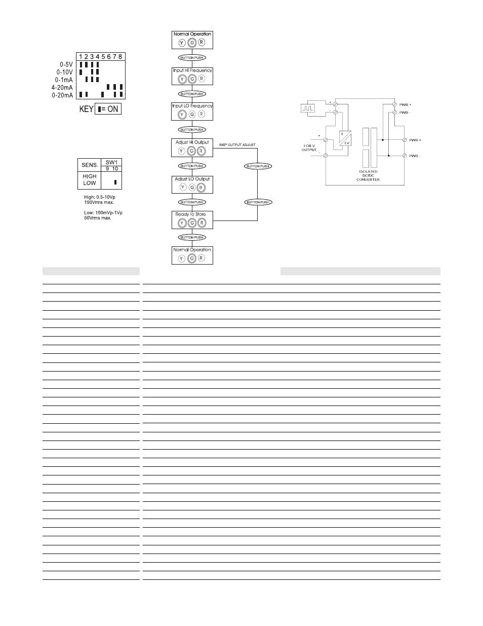
Figure 1:
G478 calibration
flow chart
Table 1: Output switch settings
(SW1, 1 through 8)
Table 2: Input amplitude threshold
sensitivity settings