Weidmuller G448 Ultra SlimPak User Manual
Page 3
A major advantage of the G448 is its wide ranging capabilities and ease of configuration. The G448 has 11
input range switch settings. Trim potentiometers allow 50% input zero and span adjustablity within each of
the 11 full-scale, input ranges.
For example, the 200mV switch setting in Table 1 configures the input for a 0 to 200mV range. Since the
span can be contracted by 50%, this enables an input span as narrow as 100mV of the range, or 50%. This
span can be positioned anywhere within the 0-200mV range with a zero offset as large as 50% of the full
scale range (e.g. 100 to 200mV input). Unless otherwise specified, the factory presets the Model G448 as
follows:
Input Setting: 0 to 50mV
Input Range: 0 to 30mV (3mV/V)
Excitation: 10V
Operation: Direct
Output: 4 to 20mA
The DC power input accepts any DC source between 18 and 30V, typically a 24Vdc source is used.
For other I/O ranges refer to Tables 1 through 4 and reconfigure switches SW1 and SW2 for the desired
input range, function, excitation and output range.
Do not attempt to change any switch settings with power applied. Severe damage will result!
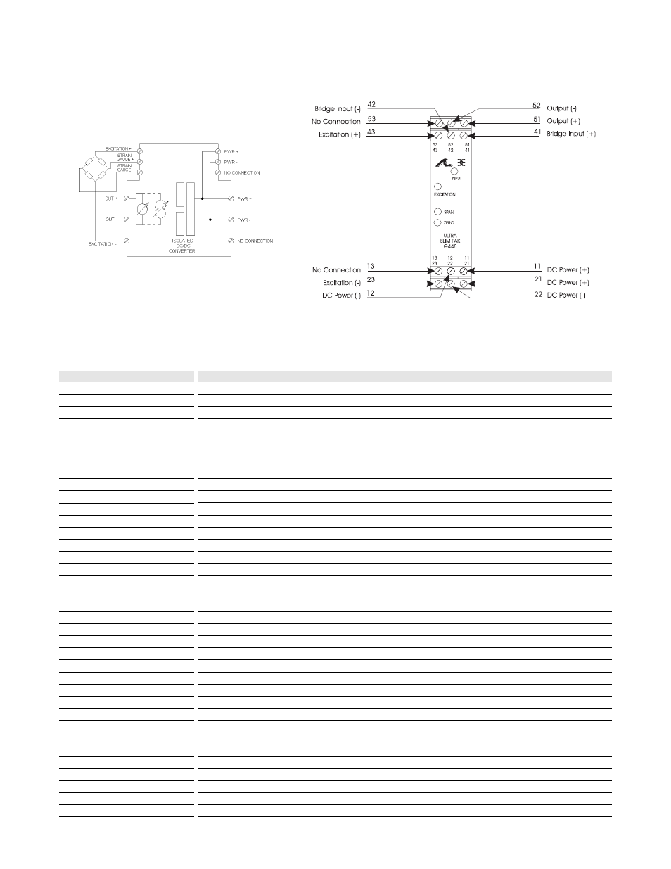
1. After configuring the DIP switches, connect the input to a calibrated millivolt source. Connect the output
to the actual device load (or a load equivalent to the actual device load value) and apply power. (see Wiring
Diagram).
NOTE: To maximize thermal stability, final calibration should be performed in the operating installation,
allowing approximately 1 to 2 hours for warm up and thermal equilibrium of the system.
2. Set the calibrator to the desired minimum and adjust the zero potentiometer for the desired minimum
output.
3. Set the calibrator to the desired maximum and adjust the span potentiometer for the desired maximum
output.
4. Repeat steps 2 and 3, if necessary for best accuracy.
5. Connect a calibrated voltmeter to the excitation output and adjust the excitation potentiometer to the
desired voltage output.
Configuration
WARNING:
Calibration