Weidmuller G428 Ultra SlimPak User Manual
Page 2
Description
Application
Diagnostic LEDs
Input LED
CAL OK LED
Troubled LED
The G428 is a DIN rail mount, thermocouple input signal conditioner with 1800Vdc isolation between input,
output and power. The field configurable input and output offer flexible, wide ranging capability for J, K, T, R,
S, E and B type thermocouples.
The input of the G428 can be configured for over 60 different thermocouple temperature ranges (see
Table 6). The output is linear to temperature and can be set for either 0-5V, 0-10V, 0-1mA, 0-20mA or
4-20mA.
Wide ranging, precision zero and span pots allow 50% adjustablity of offset and span turn-down within each
of the ranges. For example, the 0-1000°C range could be offset and turned down to provide a 4-20mA
signal representing 500-1000°C. Similarly, adjustment can be referenced to the output range. The example
from above could be used to provide a 12-20mA signal from a 750 to 1000°C temperature input.
The G428 field configurable thermocouple input isolator is useful in eliminating ground loops and interfacing
thermocouple sensors to data acquisition and control systems.
Three way isolation completely eliminates ground loops from any source. Isolation protects expensive
SCADA systems from ground faults and allows the noise reduction benefits of grounded thermocouples to
be realized.
The G428 employs the latest in advanced analog signal processing technology. In addition to its multiple
microprocessors, a special ASIC chip is used for high accuracy and reliability. The G428 is also equipped
with cold junction compensation (CJC) circuitry to provide ice-point reference. Upscale or downscale
thermocouple burnout detection is switch selectable. High density DIN rail mounting offers an extremely
compact solution to save valuable panel space.
The G428 is equipped with front panel LEDs for INPUT (green), TROUBLE (yellow) and CAL OK (yellow). At
start-up, both the INPUT and the CAL OK LEDs flash alternately for 10 seconds while start-up takes place.
This green LED is lit continuously when the input is within the specified range. In the full temperature range
setting, for the over range condition the LED flashes at 8Hz, whereas for the under range condition it flashes
at 4Hz. In a sub-range temperature setting, for the over range condition the LED flashes at 1Hz, whereas for
the under range condition it flashes at 0.5Hz.
This yellow LED is continuously on when the device is calibrated.
This yellow LED is off during the normal operation of the device. Consult factory if this LED is on, indicating
a microprocessor malfunction.
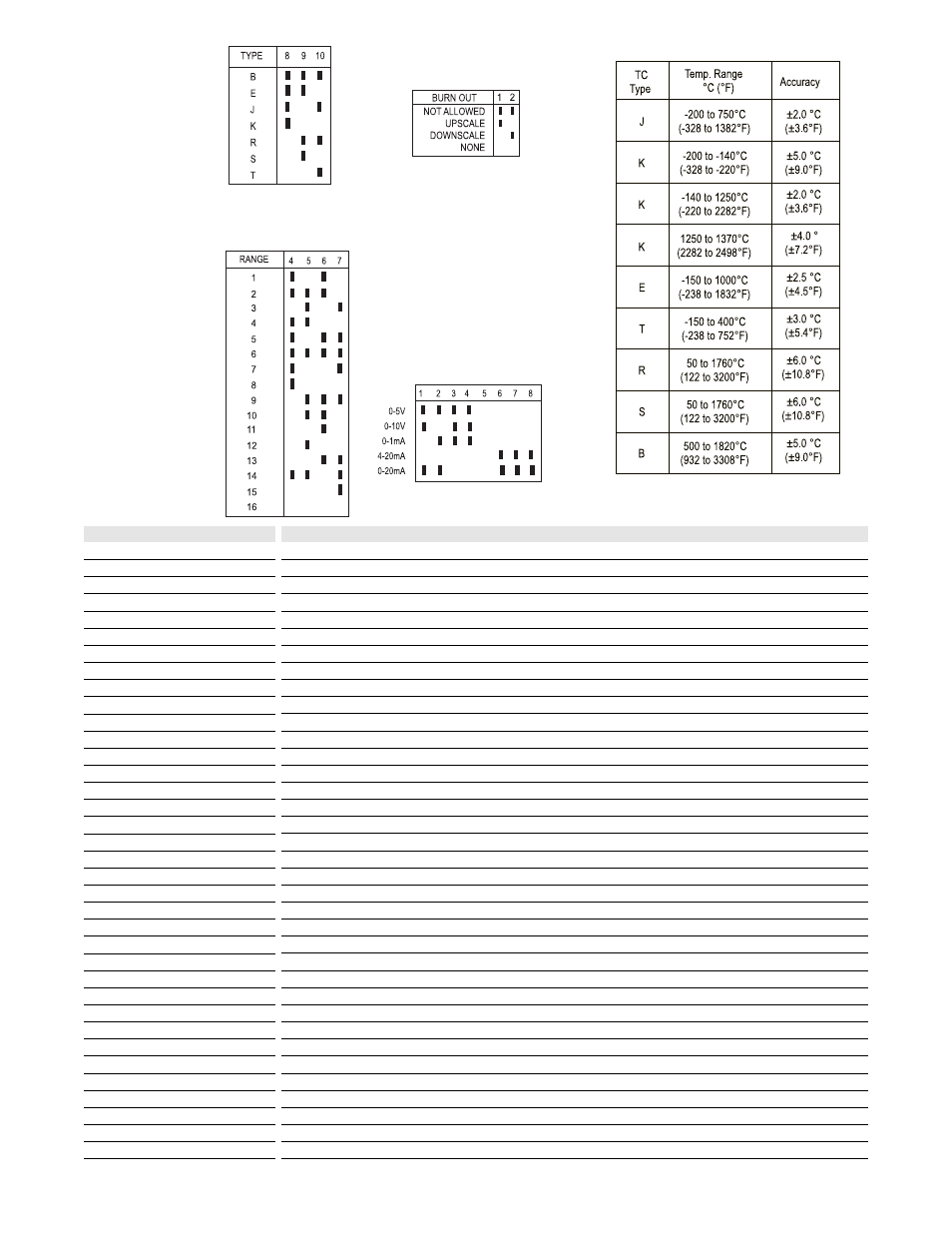
Table 2:
Range switch settings used
in conjuction with Table 6
(SW2, positions 4,5,6 and 7
Table 1:
Thermocouple type switch
settings (SW2, position 8, 9,
10)
Table 4:
Output switch settings
(SW1, position 1-8)
Table 5: Accuracy
Table 3:
Thermocouple burnout detection
switch settings (SW2, position 1, 2)
Note: SW2 position 3 is not used.
Key:
n ON