Installation and operation, 2 pre-installation preparation – WarmlyYours TempZone Floor Heating Cable (Twin) User Manual
Page 13
Installation and Operation
SECTION 5
10
5.2 Pre-Installation Preparation
5.2.1 Document the plan. Follow a SmartPlan™ obtained from WarmlyYours or prepare a floor plan of the area to be heated. Using
a floor plan, with the TempZone™ Floor Heating Cable (Twin) layout marked, makes it easy to trace the heating cable routing
for troubleshooting if necessary.
5.2.2 Select the appropriate TempZone™ Floor Heating Cable (Twin), ensuring it is the correct length and voltage.
5.2.3 Identify a suitable location for installing the thermostat and low-voltage sensor if used.
5.2.4 Mark the layout of the floor heating cable on the floor plan. Taking photographs of the area may also be helpful.
5.2.5 Inspect the TempZone™ Floor Heating Cable (Twin) visually and ensure that it is not damaged. Check voltage, wattage, and
resistance values on the label.
5.2.6 Proper surface preparation of floor is extremely important. Make absolutely sure that there are no objects on the floor
that might damage the TempZone™ Floor Heating Cable (Twin). Sweep the floor to ensure it is completely clear of debris,
including nails, sharp metallic objects, wood, construction debris, and damaged or defective cables.
5.2.7 If applicable, install CeraZorb® on the concrete subfloor. Follow the manufacturer’s instructions when installing the
CeraZorb® insulating underlayment.
5.2.8 Check resistance of TempZone™ Floor Heating Cable (Twin) with an ohmmeter or PowerMan™ upon removing it from
the package. Refer to section 5.3 for instructions on how to perform the testing using an ohmmeter or PowerMan™. The
resistance value of the heating cable should match the value on the label attached to the cable with a tolerance of -5/+10%
allowed at 20º C (68º F). Record the resistance value on the warranty card in section 10.
IMPORTANT:The electrical resistance of the cable must be checked before you begin and monitored
throughout the installation process to ensure there has been no damage causing shorts or breaks.
WarmlyYours recommends at least three readings be taken:
1. Before starting installation
2. After securing the cable in place on the subfloor
3. After installing the flooring surface on top of the cable
5.2.9 Using an ohmmeter or PowerMan™, check the insulation resistance of the cable between the core wires
and to the ground wire. It should always read infinity.
5.2.10 Use a Circuit Check™ or PowerMan™ device during cable installation. These devices will provide an
audible alarm if the wire is damaged or cut during installation. A continuity checker is not acceptable
for these tests
IMPORTANT: Beware of Using a Continuity Checker!
For cables that have over 200 Ω resistance, some continuity checkers do not send enough current to
get completely through the wire and emit the noise or light that affirms proper continuity. Please use a
digital ohmmeter.
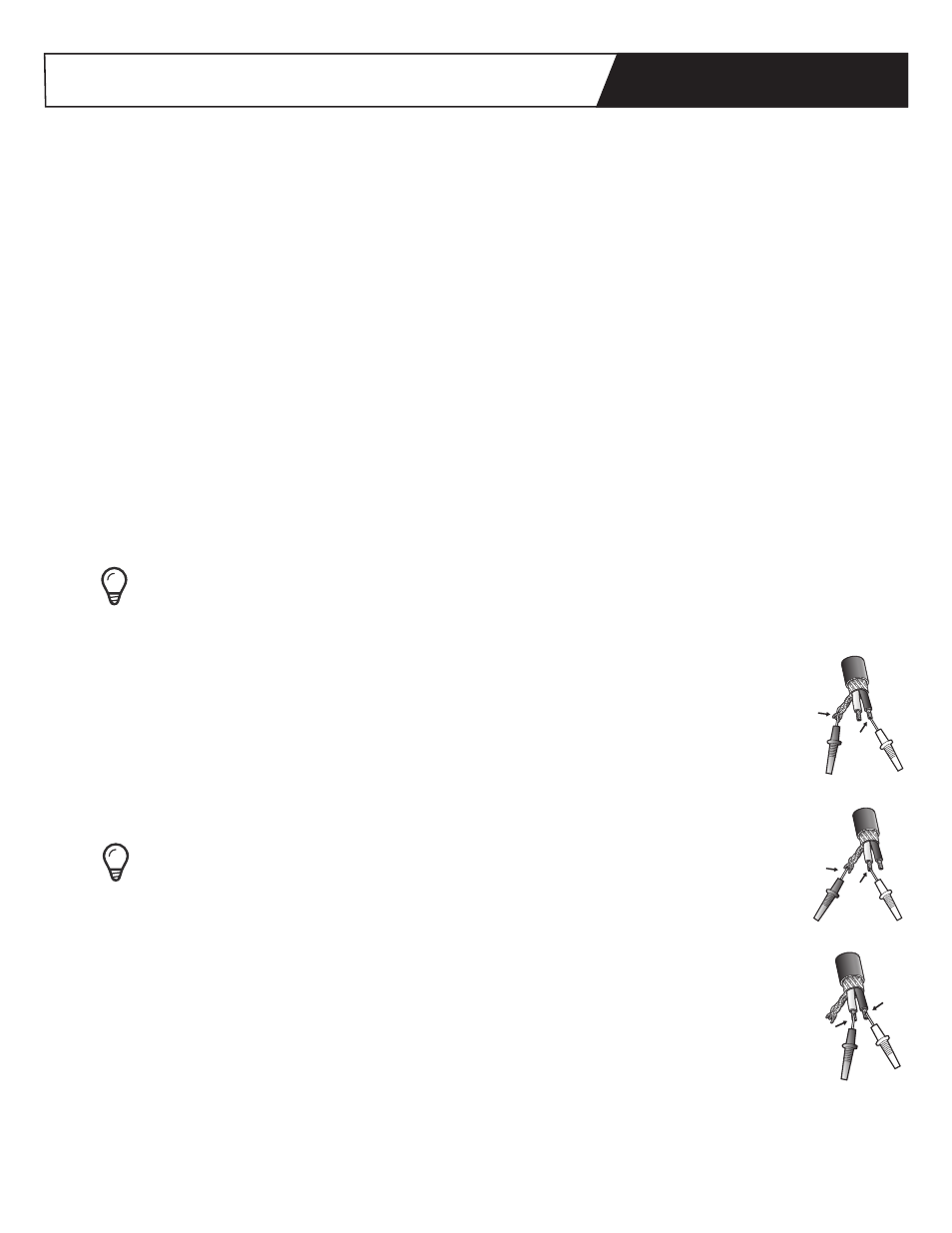
Three (3) ohm readings should be taken for each WarmlyYours TempZone™ Floor Heating Cable at each
stage of the installation and recorded in the table on the warranty card in section 10. Refer to Figure 2
for instructions about how to attach the ohmmeter or PowerMan™ to take each type of reading.
1. Core to Core: This is the reading between the two inner conductors on the lead wires.
2. Core to Sheath, Yellow / Red Lead: This is the reading between the inner core and the outer
ground sheath on the lead wire. This reading should be infinity.
3. Core to Sheath, Black Lead: This is the reading between the inner core and the outer ground
sheath on the lead wire at the finish point of the cable. This reading should be infinity.
Figure 2.
Attachment points
for ohm readings
Yellow
or Red
Ground
Ground
Yellow
or Red
Black
Black
Core to Core
Yellow
or Red
Ground
Ground
Yellow
or Red
Black
Black
Core to Sheath
Yellow
or Red
Ground
Ground
Yellow
or Red
Black
Black
Core to Sheath