B&B Electronics 3PCI2 User Manual
Page 49
44
Chapter 6
Documentation Number 3PCI2-0903 Manual
B&B Electronics Mfg Co – 707 Dayton Rd - PO Box 1040 - Ottawa IL 61350 - Ph 815-433-5100 - Fax 815-433-5104
B&B Electronics Ltd – Westlink Comm. Pk. – Oranmore, Galway, Ireland – Ph +353 91-792444 – Fax +353 91-792445
Chapter 6:
RS-422/RS-485 Connections/Operation
These modes support 2 channels - transmit and receive. The
pinouts of the DB-9 male connector are given in Table 4.
Connect only to specified pins for proper operation.
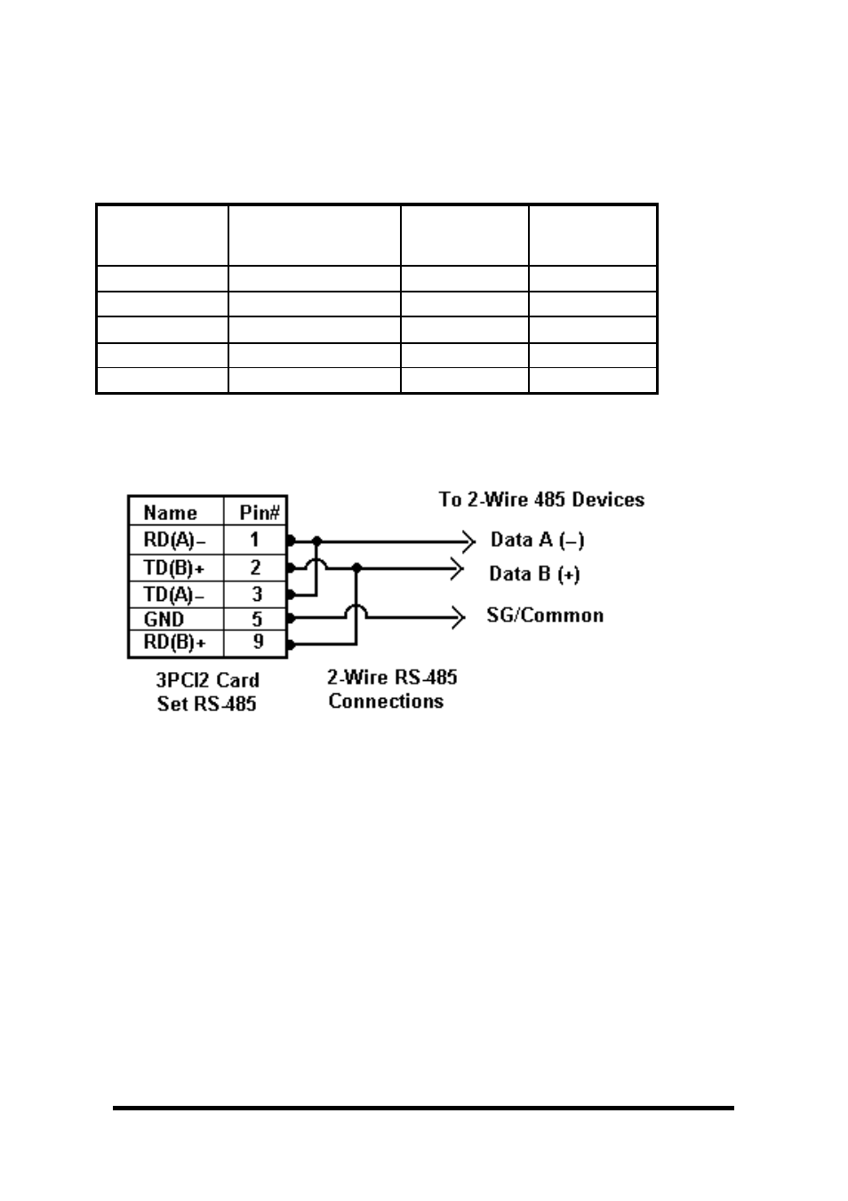
2-Wire RS-485 Connections
Fig. 6.1
2-Wire RS-485: Your cables must bridge pins #1 & #3 and pins #2 &
#9 in order to receive and transmit. Connect from Pin #2 to Data
B(+) of your devices and from pin #3 to Data A(-) of your devices.
Make sure your Mode/Jumpers are set, and that the driver Setting
for DTR Operation is RS-485 Mode in the Device Manager.
Note that the EIA RS-422 Specification labels data lines with an "A"
and "B" designator. Some RS-422 or RS-485 equipment uses a "
−
"
and "+" designator. In most cases, the "A" line is the equivalent of
the "
−
" line and the "B" line is the equivalent of the "+" line. Some
device manufacturers may not follow the standard designation for
RS-422 or RS-485, using the A connection for “+” and the B for “-“.
In such cases, reversing the line pair permits operation.
Table 4: RS-422/485 Pinouts
Name
Description
Direction
DB9M
Pin
RD(A)
−−−−
Receive Data A
Input
1
TD(B) +
Transmit Data B
Output
2
TD(A)
−−−−
Transmit Data A
Output
3
GND
Signal Ground
------
5
RD(B) +
Receive Data B
Input
9