Selection of operating mode, Port 1 (bottom connector), Port 2 (top connector – B&B Electronics 3PCI2 User Manual
Page 11
6
Chapter 3
Documentation Number 3PCI2-0903 Manual
B&B Electronics Mfg Co – 707 Dayton Rd - PO Box 1040 - Ottawa IL 61350 - Ph 815-433-5100 - Fax 815-433-5104
B&B Electronics Ltd – Westlink Comm. Pk. – Oranmore, Galway, Ireland – Ph +353 91-792444 – Fax +353 91-792445
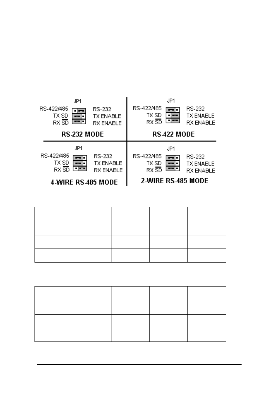
Selection of Operating Mode
The hardware address and IRQ is set by the Windows Operating
System using driver information files and the Plug and Play OS.
The Operating Mode is set using Jumpers, Device Manager Driver
Settings and by your cable connections and software.
Set the Jumpers
Set JP1 and JP2 Jumpers to match your Operating Mode.
Port 1 (bottom connector)
Port 1
Jumpers
RS-232
RS-422
4-Wire
RS-485
4-Wire
RS-485
2-Wire
JP1 Top
232
(Right)
422/485
(left)
422/485
(left)
422/485
(left)
JP1 Middle
-----
No effect
TX ENABLE
(right)
TX SD
(left)
TX SD
(left)
JP1 Bottom
-----
No effect
RX ENABLE
(right)
RX ENABLE
(right)
RX SD
(left)
Table 1 – Port 1 (near bus) Jumper/Mode Table
Port 2 (top connector
)
Port 2
Jumpers
RS-232
RS-422
4-Wire
RS-485
4-Wire
RS-485
2-Wire
JP2 Top
232
422/485
(left)
422/485
(left)
422/485
(left)
JP2 Middle
-----
No effect
TX ENABLE
(right)
TX SD
(left)
TX SD
(left)
JP2 Bottom
-----
No effect
RX ENABLE
(right)
RX ENABLE
(right)
RX SD
(left)
Table 2 – Port 2 (near top of card) Jumper/Mode Table