Installation, Standing pilot and heat exchange return, Installing the heat exchanger return – Regency Liberty L540EB Large Gas Insert User Manual
Page 29
L540E-2 / HZI540E-2 Direct Vent Gas Insert
29
INSTALLATION
The L540E / HZI540E use a heat exchanger and effi cient combustion
technology to provide extreme heating effi ciencies. The more effi cient an ap-
pliance becomes, the lower the fl ue gas temperatures becomes.
On start-up, fl ue temperatures are required to initiate venting action.
Here are some considerations when setting up the L540E / HZI540E:
1) When operating the unit in temperatures below 50° F, run the pilot in
"Standing Pilot" mode, by setting the Surefi re™ switch to ON.
The switch is located to the bottom left of the Firebox Door.
Move the switch to the right to run in Standing Pilot mode, to the left to
run in Intermittent Pilot (electronic ignition) mode. This will aid in keeping
the fl ue slightly warmer than the outside air, making start up a smoother
process.
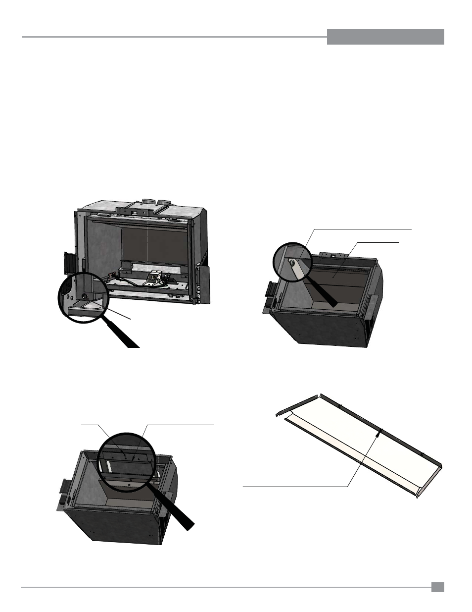
STANDING PILOT AND HEAT EXCHANGE RETURN
Standing
Pilot On/Off
2) The "Heat Exchanger Return"may be installed in circumstances where
the maximum effi ciency is desired. This will require that the unit is run in
standing pilot mode only, as the Heat Exchanger return presents
additional restriction to the fl ue system.
Exhaust Baffle
Screws help to locate
the Exhaust Baffle when
installing in the Firebox
Exhaust Baffle
Exhaust Baffle Screws (both sides)
Exhaust Baffle
Screw
Heat Exchanger Return
Heat Exchanger Return
INSTALLING THE HEAT EXCHANGER RETURN
1) Remove the left and right side panels. Remove one screw in the upper
left and upper right of the fi rebox as shown below. Once the screws
have been removed, lower the front edge of the exhaust baffl e and pull
towards you. There are 3 screws at the rear of the exhaust baffl e that
help to position the baffl e and keep it straight during operation.
2) If the unit has been previously operated, spray the fasteners with WD-40
and let them sit for a few minutes. Remove the screw that holds the heat
exchange return in place. Insert the Heat Exchanger Return up inside
the head exchanger. Some clearance holes are provided to fi t around
existing fasteners. re-install the screw(s) that will hold the Heat Exchang-
er Return in place. Re-install the Exhaust Baffl e and Panels.
Surefi re switch for standing pilot