Installation, Optional fan wiring diagram, Without proflame gtmf system – Regency Horizon HZ40E Medium Gas Fireplace User Manual
Page 41: Fan thermodisc (normally open), Ground
Regency Horizon™ HZ40E-2 Gas Fireplace
41
INSTALLATION
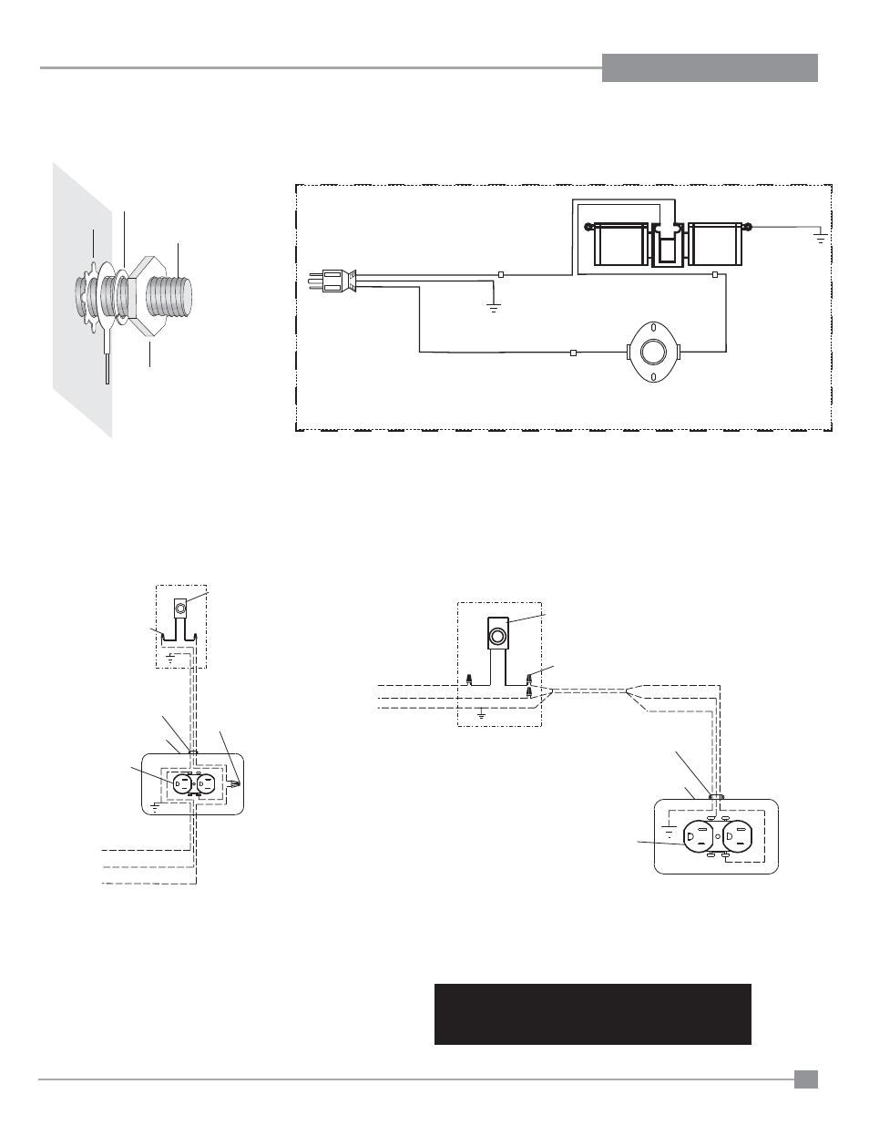
Ground
Green
Neutral
Live
Black
Red
Black
Fan Thermodisc
(normally open)
120V AC
60 Hz
White
Black
Black
Ground
Fan
Fan
CAUTION: Label all wires prior to disconnection
when servicing controls. Wiring errors can cause
improper and dangerous operation.
Lockwasher
Fan
ground wire
Nut
#8 Ground Lug
(for mobile home)
Star washer
OPTIONAL FAN WIRING DIAGRAM
WITHOUT PROFLAME GTMF SYSTEM
Electrical Connection Alternative Scheme "A",
Power at Stove
Wall Junction Box
*Speed Control
Switch with
lead wires
(Regency)
Wire Nuts
Wire Nuts
14 AWG wire
14 AWG wire
*Wire Clamp
*Receptacle Box
inside stove
*Receptacle
(dedicated use
by stove fan only)
120 Volts
60 Hz
Copper Ground
White (Neutral)
Black (Hot)
~
Electrical Connection Alternative Scheme "B",
Power at Switch
Wall Junction Box
*Speed Control
Switch with lead wires
Wire Nuts
14 AWG wire
*Wire Clamp
120 Volts
60 Hz
Copper Ground
White (Neutral)
Black (Hot)
Wire
Black
White
Ground
*Receptacle Box
inside stove
~
*Receptacle
(dedicated use
by unit fan only)
* = supplied with fan kit
Other parts are to be supplied
by electrician or installer
Caution: Ensure that the wires do not touch any
hot surfaces and are away from sharp edges.