Installation, Proflame system gt proflame system gtm, Wiring diagram – Regency Horizon HZ40E Medium Gas Fireplace User Manual
Page 39
Regency Horizon™ HZ40E-2 Gas Fireplace
39
INSTALLATION
CAUTION: Label all wires prior to disconnection
when servicing controls. Wiring errors can cause
improper and dangerous operation.
Caution: Ensure that the wires do not touch any
hot surfaces and are away from sharp edges.
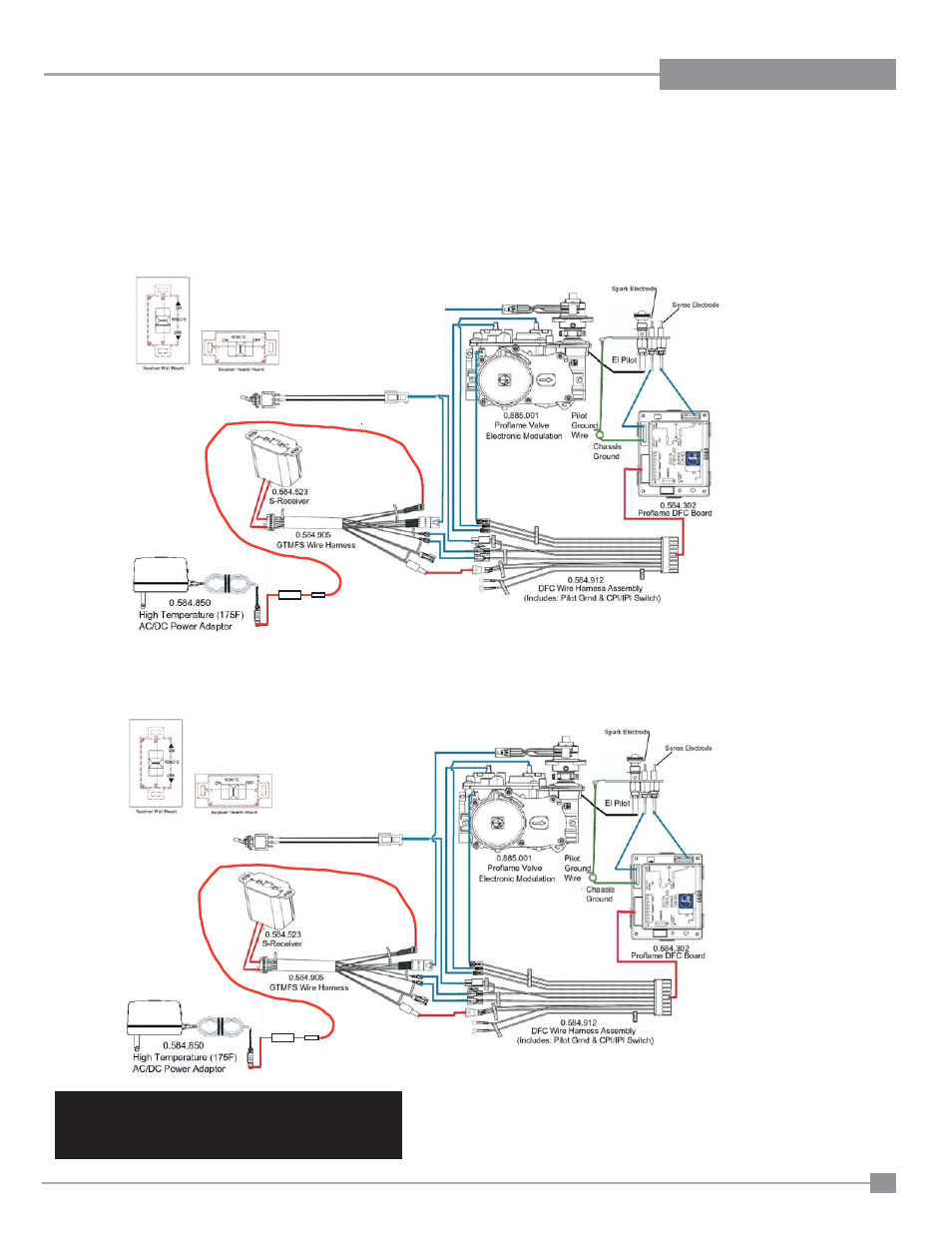
PROFLAME SYSTEM GT
PROFLAME SYSTEM GTM
Proflame System
Configuration
886 GTMF
Wire Diagram
SureFire™ Switch
885
Optional AC Adaptor
Proflame System
Configuration
886 GTMF
Wire Diagram
SureFire™ Switch
885
Optional AC Adaptor
WIRING DIAGRAM
This heater does not require a 120V A.C. supply for operation. In case of a power failure, the burner switch and the optional remote control/thermostat will
continue to operate. However, a 120V A.C. power supply is needed for the fan/blower operation.
(Do not cut the ground terminal off under any circumstances.)
NOTE: Even if the fan is not purchased with the unit, it is still a good idea to bring power to the receptacle box (provided with the unit) in case the
fan is installed at a later date.
- Alterra CI1200 Small Wood Insert (32 pages)
- Alterra CS1200 Small Wood Stove (32 pages)
- Alterra CS2400 Medium Wood Stove (32 pages)
- Bellavista B36XTCE Medium Gas Fireplace (72 pages)
- Bellavista B36XTE Medium Gas Fireplace (72 pages)
- Bellavista B41XTCE Large Gas Fireplace (68 pages)
- Bellavista B41XTE Large Gas Fireplace (64 pages)
- CI2600 Large Wood Insert (40 pages)
- Classic C34 Small Gas Stove (44 pages)
- Classic F3100 Large Wood Stove (28 pages)
- Classic F2400 Medium Wood Stove (28 pages)
- Classic F5100 Extra Large Wood Stove (36 pages)
- Classic H2100 Hearth Heater Wood Insert (24 pages)
- Classic I1200 Small Wood Insert (24 pages)
- Classic I2400 Medium Wood Insert (20 pages)
- Classic R90 Large Wood Fireplace (Canadian Edition) (40 pages)
- Classic R90 Large Wood Fireplace (US Edition) (36 pages)
- Energy U21 Small Gas Insert (40 pages)
- Energy U31 Medium Gas Insert (36 pages)
- Energy U32 Medium Gas Insert (44 pages)
- Excalibur E33 Large Gas Insert (44 pages)
- Excalibur P90 Medium Gas Fireplace (56 pages)
- Greenfire GF55 Medium Pellet Insert (16 pages)
- Hampton GC60 Large Pellet Stove OWNER'S MANUAL (18 pages)
- Hampton GC60 Large Pellet Stove TECHNICAL MANUAL (32 pages)
- Hampton GCI60 Large Pellet Insert OWNER'S MANUAL (18 pages)
- Hampton GCI60 Large Pellet Insert TECHNICAL MANUAL (34 pages)
- Hampton H15 Small Gas Stove (48 pages)
- Hampton H200 Medium Wood Stove (36 pages)
- Hampton H27 Medium Gas Stove (48 pages)
- Hampton H300 Large Wood Stove (36 pages)
- Hampton H35 Large Gas Stove (48 pages)
- Hampton HI200 Small Wood Insert (24 pages)
- Hampton HI300 Medium Wood Insert (32 pages)
- Horizon HZ30E Small Gas Fireplace (64 pages)
- Horizon HZ33CE Small Gas Fireplace (60 pages)
- Horizon HZ42STE Medium Gas Fireplace (60 pages)
- Horizon HZ54E Large Gas Fireplace (68 pages)
- Horizon HZ965E Large Gas Fireplace (68 pages)
- Horizon HZI234E Small Gas Insert (52 pages)
- Horizon HZI390EB Medium Gas Insert (60 pages)
- Horizon HZI540EB Large Gas Insert (56 pages)
- Horizon HZO42 Outdoor Gas Fireplace (44 pages)
- Liberty L234 Small Gas Insert (44 pages)